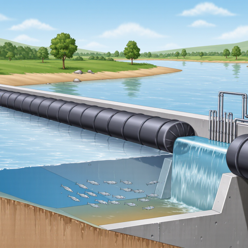
| 1. Site Selection and Design Parameters |
| Site conditions | Suitable river section | Straight or gently curved reach with stable banks, a firm foundation, and manageable sediment transport | Geotechnical assessment before design | Avoid active meander bends, unstable banks, severe scour zones, and locations with uncontrolled debris accumulation. |
| Water level control | Normal upstream operating level | Set by the hydraulic design and permitted water-use requirements; maintain adequate freeboard below adjacent flood-sensitive areas | Confirm during design and commissioning | The operating level must account for seasonal flow, flood discharge, downstream effects, and environmental requirements. |
| Rubber body | Typical construction | Fabric-reinforced elastomeric membrane, commonly produced with multiple reinforcement plies | Material verification before installation | Final elastomer type, reinforcement, thickness, and allowable pressure must be specified by the engineering design. |
| Dam height | Typical low-head application range | Approximately 1.0–5.0 m, subject to hydraulic, structural, and regulatory approval | Review during design verification | Higher installations require more detailed stability, anchorage, flood-routing, and emergency-deflation analysis. |
| Foundation | Foundation requirements | Level, clean, adequately bearing, and protected against piping, uplift, and local scour | Inspect before concrete placement and after major floods | Foundation treatment may include cutoff elements, grout, filter layers, riprap, or other engineered scour protection. |
| Hydraulic safety | Flood passage | Provide a reliable automatic or controlled deflation method so floodwater can pass without overtopping the rubber body | Test before each flood season | Do not depend on manual response alone where river levels can rise faster than operators can reach the site. |
| 2. Main System Components |
| Rubber dam body | Primary water-retaining element | Flexible, fabric-reinforced membrane anchored continuously to the foundation | Visual inspection monthly and after abnormal events | Look for cuts, abrasion, blisters, permanent deformation, exposed reinforcement, and chemical deterioration. |
| Anchorage system | Base plate, bolts, clamps, and sealing arrangement | Continuous watertight anchorage designed for hydrostatic, uplift, and sliding forces | Inspect at least annually | Check bolt condition, clamp alignment, corrosion, seal compression, concrete cracking, and leakage paths. |
| Inflation or control system | Air or water filling arrangement | Includes blower or pump, valves, pressure measurement, non-return protection, and isolation devices | Functional test monthly during operating season | All isolation valves should be clearly labeled and accessible for emergency operation. |
| Deflation system | Normal and emergency release | Controlled discharge path with manual and, where required, automatic activation | Test before flood season and after modifications | Discharge must be directed safely and must not erode the foundation, riverbank, or nearby structures. |
| Monitoring devices | Pressure and water-level instruments | Pressure gauge or sensor, upstream and downstream level gauges, and alarm or telemetry where appropriate | Check readings during every operating shift | Instrument readings should be compared with independent visual water-level observations. |
| 3. Installation Procedure |
| Pre-installation survey | Dimensions and level verification | Confirm dam width, foundation elevations, anchor locations, access routes, and temporary river diversion arrangements | Before delivery and construction | Record as-built elevations and check that the prepared foundation matches the approved drawings. |
| Foundation preparation | Surface condition | Remove sharp stones, loose material, standing water, oil, and construction debris; repair honeycombing and major defects | Immediately before membrane placement | Sharp edges can puncture or abrade the membrane during inflation and repeated operation. |
| Membrane handling | Transport and placement | Use clean lifting methods and broad supports; do not drag the membrane over concrete, gravel, or reinforcing steel | Throughout installation | Protect the membrane from welding sparks, solvents, fuels, direct mechanical impact, and prolonged unnecessary sunlight exposure. |
| Anchoring | Anchor installation sequence | Align the membrane, install seals and clamps evenly, and tighten fasteners progressively according to the approved procedure | During installation and final inspection | Uneven clamping can create leakage, wrinkles, concentrated stress, and premature wear. |
| Pressure testing | Initial inflation test | Inflate gradually while checking pressure, alignment, leakage, anchor movement, and membrane behavior | Before first full operation | Use the specified design pressure; never exceed the maximum allowable pressure stated for the installed system. |
| Commissioning | Functional test | Verify inflation, partial deflation, full deflation, alarms, level response, isolation valves, and emergency procedures | Before acceptance and after major repair | Document test results, measured pressures, water levels, leakage observations, and corrective actions. |
| 4. Operation and Water-Level Control |
| Normal operation | Pressure control | Maintain pressure within the approved operating range and adjust gradually to prevent sudden level changes | Continuous or scheduled monitoring | Pressure values must be interpreted together with water level, temperature, membrane condition, and river flow. |
| Water-level adjustment | Inflation and deflation rate | Make controlled changes in stages; avoid rapid manipulation unless required by an emergency procedure | Whenever operating level changes | Rapid drawdown can increase bank instability, expose aquatic habitat, and cause sediment movement. |
| Flood response | High-flow action | Prepare for controlled deflation when forecast flow or upstream level approaches the approved trigger condition | During flood watches and high-flow events | Trigger levels must be established by the project engineer using local hydrology and downstream risk. |
| Debris management | Floating logs, branches, and ice | Remove accumulated debris using safe methods and keep it from contacting the membrane or control equipment | After storms and during high-flow periods | Personnel must not stand on, walk across, or work directly against a pressurized rubber dam body. |
| Environmental control | Fish passage and water quality | Operate according to applicable permits, minimum-flow requirements, fish-passage provisions, and water-quality limits | Continuous compliance monitoring where required | Water-level control should not obstruct legally required aquatic passage or cause unacceptable upstream stagnation. |
| Emergency action | Loss of pressure or membrane damage | Isolate the system, warn affected personnel, assess downstream risk, and deflate if required | Immediately after alarm or abnormal observation | Use the approved emergency action plan and notify responsible authorities when public safety or flooding may be affected. |
| 5. Inspection and Maintenance Schedule |
| Routine visual inspection | Membrane, anchors, valves, and surrounding area | Check for leakage, abrasion, cuts, abnormal folds, corrosion, loose hardware, vibration, and obstruction | Weekly during active operation; monthly during low-use periods | Record date, weather, river condition, pressure, upstream level, downstream level, and observed defects. |
| Pressure verification | Gauge and sensor accuracy | Compare installed readings with a calibrated reference instrument or approved verification method | At least annually and after suspicious readings | A gradual unexplained pressure decline may indicate leakage, valve failure, temperature effects, or membrane damage. |
| Valve and blower/pump service | Mechanical and electrical equipment | Inspect seals, filters, lubrication points, electrical connections, non-return devices, and protective enclosures | According to equipment condition and the maintenance schedule | Disconnect and lock out energy sources before servicing rotating or pressurized equipment. |
| Anchor and concrete inspection | Fasteners, clamps, seals, and foundation | Check for corrosion, loosening, cracking, spalling, leakage, settlement, and undermining | Every six to twelve months and after major floods | Any loss of anchorage integrity requires engineering assessment before returning to normal operation. |
| Scour and bank inspection | Upstream, downstream, and abutment protection | Inspect for erosion holes, exposed foundation, displaced rock, bank slumping, and seepage | After every significant flood or rapid drawdown | Repair erosion promptly because local scour can progress beneath the structure without obvious surface warning. |
| Membrane cleaning | Surface deposits and biological growth | Use clean water and non-damaging methods; remove sharp debris without abrasive tools or harsh solvents | As required, normally once or twice per year | Cleaning methods must be compatible with the membrane material and local environmental requirements. |
| Repair assessment | Cuts, punctures, or delamination | Stop normal operation and obtain qualified technical assessment for significant damage | Immediately after discovery | Temporary patches should only be used when approved; permanent repairs require compatible materials and controlled surface preparation. |
| Post-flood inspection | Complete condition assessment | Inspect the membrane, anchorage, foundation, control system, riverbanks, debris field, and instrumentation | As soon as safe access is available after each major flood | Photograph defects and compare current observations with previous inspection records. |
| 6. Safety, Records, and Service Life |
| Personnel safety | Work near a pressurized dam | Restrict access, use appropriate personal protective equipment, and follow lockout, confined-space, and water-safety procedures | At every inspection and maintenance activity | Never climb onto the membrane, work below suspended loads, or approach rapidly moving water without a site-specific risk assessment. |
| Inspection records | Minimum record content | Date, operator, weather, flow condition, pressure, water levels, equipment status, defects, photos, and corrective actions | Update after each inspection or operational event | Trend records help identify slow leakage, settlement, sensor drift, and recurring debris or scour problems. |
| Spare parts | Recommended stock | Compatible seals, approved repair materials, fasteners, valve components, gauges, fuses, filters, and emergency tools | Review inventory every six months | Store elastomer-compatible parts in a dry, clean location protected from heat, ozone, oils, and direct sunlight. |
| Expected service life | Planning reference | Often designed for several decades, but actual life depends on material quality, ultraviolet exposure, abrasion, chemicals, floods, and maintenance | Formal condition assessment at regular engineering intervals | Service life is not guaranteed by age alone; replacement planning should be based on measured condition and risk. |
| Regulatory compliance | Permits and approvals | Follow applicable dam-safety, water-resource, environmental, occupational-safety, electrical, and construction requirements | Review before construction and whenever regulations change | Local authorities may require approved drawings, operating rules, emergency plans, inspections, and incident reporting. |



 Close
Close