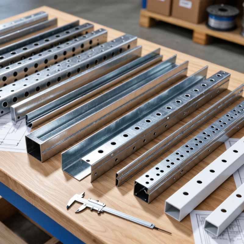
| Basic Definition | Steel cable tray system | Open support structure manufactured from formed steel sections, fittings, covers, and accessories | Supports and routes power, control, instrumentation, and communication cables while allowing ventilation and access | Commercial buildings, industrial facilities, infrastructure, energy, and data installations | Confirm cable quantity, cable weight, environmental exposure, span, and local installation requirements before selection |
| Ladder Tray | Steel ladder cable tray | Typical widths: 150–900 mm; typical side-rail height: 50–150 mm; common span: approximately 1.5–3.0 m | Longitudinal side rails and regularly spaced rungs carry cables and provide convenient tie-down points | Heavy power cables, industrial plants, substations, tunnels, and long straight cable routes | Offers strong ventilation and high cable accessibility; verify rung spacing for small or flexible cables |
| Perforated Tray | Perforated steel cable tray | Typical widths: 50–600 mm; typical side-rail height: 25–100 mm; perforated base supports cable fastening | Perforations allow cable ties, clamps, and ventilation openings while the tray base provides continuous cable support | Control cables, power distribution, building services, and mixed cable installations | A practical general-purpose option; check hole size, open-area ratio, and allowable load for the selected span |
| Solid-Bottom Tray | Solid-bottom steel cable tray | Typical widths: 100–600 mm; typical side-rail height: 50–100 mm; base has no continuous perforation | Provides continuous bottom support and greater physical separation from dust, falling particles, and nearby services | Low-voltage control, instrumentation, clean routing areas, and cables requiring additional mechanical support | Ventilation is lower than in ladder or perforated trays; cable derating and heat dissipation must be assessed |
| Wire Mesh Tray | Welded steel wire mesh tray | Typical widths: 50–600 mm; typical side height: 35–100 mm; supplied in modular straight sections and fittings | Welded wire grid supports cables, enables strong airflow, and permits cable exits at many points | Data centers, telecommunications, control systems, and short-to-medium cable routes | Lightweight and easy to modify; confirm wire diameter and load capacity for large or heavy cables |
| Material | Carbon steel | Common structural material; thickness often selected in the approximate range of 1.2–3.0 mm depending on load and span | Formed steel members resist bending and transfer cable loads to supports and building structures | Indoor commercial and industrial installations where corrosion exposure is controlled | Material thickness alone does not determine capacity; profile geometry, span, joints, and support configuration are also important |
| Surface Protection | Pre-galvanized steel | Zinc coating is applied to steel sheet before fabrication; coating mass varies by applicable standard and sheet grade | The zinc layer provides sacrificial corrosion protection for indoor and moderately controlled environments | Indoor buildings, electrical rooms, warehouses, and covered service areas | Cut edges and fabricated areas may require suitable corrosion protection; confirm coating specification with the project standard |
| Surface Protection | Hot-dip galvanized steel | Fabricated steel is immersed in molten zinc; coating thickness depends on steel thickness and the applicable galvanizing standard | A metallurgically bonded zinc coating protects the steel against atmospheric corrosion and provides sacrificial protection | Outdoor infrastructure, industrial plants, utility corridors, and humid environments | Inspect coating continuity, drainage holes, threaded connections, and compatibility with the installation environment |
| Surface Protection | Powder-coated or painted steel | Organic finish applied over prepared steel; color and coating system are project-specified | The coating forms a barrier against moisture and chemicals and can provide color identification | Indoor areas, architectural installations, and environments requiring color coordination | Surface preparation and coating adhesion are critical; damaged areas should be repaired according to the coating system |
| Corrosion Environment | Indoor dry environment | Low humidity and limited exposure to water, salt, chemicals, or industrial contaminants | Steel tray primarily provides mechanical support, with surface protection selected for expected indoor exposure | Office buildings, commercial facilities, electrical rooms, and enclosed plant areas | Pre-galvanized or suitably painted steel is commonly considered, subject to the project specification |
| Corrosion Environment | Outdoor or humid environment | Exposure may include rain, condensation, ultraviolet radiation, and temperature cycling | The tray system combines structural steel with a corrosion-resistant finish to maintain mechanical integrity over time | Roofs, bridges, external pipe racks, utility corridors, and open industrial areas | Hot-dip galvanizing or another project-approved corrosion system is generally evaluated; avoid water-retaining details |
| Corrosion Environment | Marine or chemically aggressive environment | Exposure may include salt spray, high humidity, acids, alkalis, or process chemicals | The tray must resist accelerated corrosion while maintaining support capacity and electrical bonding continuity | Coastal facilities, wastewater plants, chemical plants, offshore-related infrastructure, and food-processing areas | Material and finish should be selected through a documented corrosion assessment; stainless steel may be considered where required |
| Cable Capacity | Width selection | Common commercial widths range from approximately 50 to 900 mm; larger systems are available for engineered projects | Tray width determines the available cable arrangement space and helps prevent excessive crowding | All cable tray systems | Allow space for cable separation, installation access, future additions, bending radius, and required clearances |
| Cable Capacity | Fill planning | Actual allowable fill depends on cable type, heat dissipation, installation code, and cable arrangement | Open tray construction allows cables to be arranged for ventilation and maintenance without fully enclosing them | Power, control, instrumentation, and communication systems | Do not select tray width from cable diameter alone; check ampacity, grouping, segregation, and future capacity |
| Load Performance | Static load rating | Specified in force per unit length, commonly shown as N/m or kg/m, for a stated support span | Side rails, rungs, and tray bottoms transfer cable weight to brackets, hangers, or structural supports | All installations carrying cables or accessories | Compare load ratings only when span, tray width, support type, deflection limit, and test method are equivalent |
| Support Spacing | Horizontal support arrangement | Typical support spans are approximately 1.5–3.0 m, but the exact spacing depends on design load and manufacturer testing | Supports reduce bending and keep the tray within its permitted deflection and strength limits | Ceiling-mounted, floor-mounted, rack-mounted, and wall-mounted systems | Provide additional support near bends, tees, reducers, expansion joints, and heavy cable concentrations |
| Thermal Performance | Ventilated tray design | Ladder, perforated, and wire mesh trays provide more open area than solid-bottom designs | Airflow around cables helps dissipate heat and can support higher permissible current than enclosed routing, subject to code calculations | Power distribution and installations with significant heat generation | Cable ampacity must be calculated using the applicable electrical code and the actual cable grouping arrangement |
| Cable Protection | Tray cover | Available as solid, ventilated, peaked, or rain-shedding covers; material and finish should match the tray system | The cover reduces exposure to falling objects, dust, water dripping, sunlight, or accidental contact | Outdoor routes, industrial areas, traffic zones, and locations requiring additional cable protection | Check ventilation, cover retention, wind exposure, drainage, maintenance access, and added structural load |
| Electrical Bonding | Grounding and bonding provisions | Bonding may use listed bolted joints, bonding jumpers, or a separate protective conductor, depending on the system design | Continuity between metallic sections helps create a reliable path for fault current where the tray is designed as a bonding conductor | Metallic tray systems in low-voltage and industrial electrical installations | Follow the applicable electrical code; verify joint continuity, paint removal requirements, bonding jumpers, and fault-current capacity |
| Installation Geometry | Fittings and accessories | Common components include elbows, tees, crosses, reducers, vertical bends, couplers, brackets, clamps, and covers | Fittings maintain cable bend radius and provide continuous mechanical support through route changes | Complex building and industrial cable-routing layouts | Fitting radius must accommodate the minimum bending radius of the largest cable installed in the route |
| Standards and Testing | Product performance verification | Typical checks include load capacity, deflection, coating quality, dimensional accuracy, electrical continuity, and corrosion resistance | Testing and documented design data demonstrate that the tray can perform under specified installation conditions | International procurement and engineered projects | Request test conditions, declared support span, allowable deflection, material grade, coating details, and applicable standard references |
| Global Procurement | Technical documentation package | Recommended documents include dimensional drawings, load tables, material certificates, coating details, installation instructions, and packing lists | Documentation enables design approval, quantity calculation, installation planning, inspection, and international shipment verification | Export projects, EPC contracts, infrastructure tenders, and multi-country installations | Ensure units, tolerances, coating terminology, inspection criteria, and delivery configuration are clearly defined before purchase |
| Selection Priority | Best overall selection approach for 2026 projects | Match tray type, width, height, material, finish, load rating, support span, cover, and fittings to the actual site conditions | A correctly engineered system maintains cable support, ventilation, accessibility, protection, and long-term corrosion resistance | Global buyers comparing steel cable tray systems without relying on brand-specific data | The best tray is the one that satisfies the project load, environment, electrical, safety, installation, and documentation requirements—not simply the lowest-priced option |



 Close