| Battery cells and modules | Cells store energy electrochemically and are assembled into modules to provide the required voltage and capacity. | Electrical connections join cells within a module and link modules in the battery assembly. These connections may use busbars, welded joints, or separable connectors, depending on the design. | Connection methods and serviceability vary by battery design. Cell-level connections are not necessarily plug-in connectors. |
| Battery racks | Racks group battery modules into larger units that can be monitored and connected as part of the storage system. | Power connectors or other approved terminations carry direct current (DC) between modules, racks, and the next electrical stage. | Connector voltage, current capacity, polarity, and compatibility must match the equipment design and installation requirements. |
| DC collection and distribution | DC cabling and distribution equipment bring power from battery racks toward the power conversion system. | A BESS power connector provides a defined electrical interface between compatible cables and equipment, helping establish a secure, low-resistance current path. | Some systems use a DC combiner or other distribution equipment; the exact arrangement depends on system architecture. |
| Power conversion system (PCS) | The PCS converts battery DC power to AC power for discharge and converts incoming AC power to DC during charging. | Connectors and cable terminations link the battery-side DC circuits to the PCS in accordance with the system design. | A BESS connector does not perform DC-to-AC conversion; that function belongs to the PCS. |
| Energy management and control | Control equipment coordinates charging, discharging, monitoring, and system operation. | Separate low-voltage signal or communication connections may carry measurement, status, or control signals. They are distinct from high-power connections. | Communication interfaces and protocols vary. Power connectors should not be treated as communication connectors. |
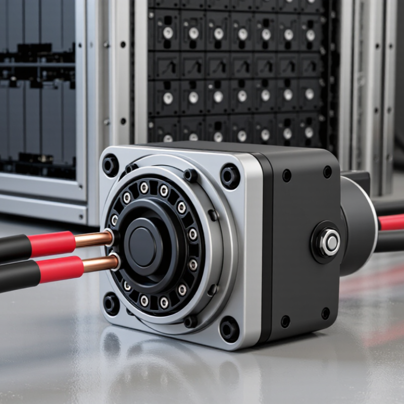
| Connector construction | A connector assembly typically includes conductive contacts, an insulating housing, and a method of securing the connection. | The contacts conduct current; the housing helps maintain electrical separation; and the mating or locking mechanism helps keep the connection engaged. | Features such as touch protection, keying, sealing, or a locking mechanism depend on the connector and application. |
| Making and maintaining a connection | A compatible connector pair is aligned, mated, and secured according to its instructions. | Correct mating establishes the intended electrical path. Disconnecting, where permitted, separates that path for approved service procedures. | Connectors must be used within their rated conditions. Installation and maintenance should follow the equipment manufacturer’s instructions and applicable electrical codes. |
| Protection and safe servicing | System protection and operating procedures help reduce electrical and thermal hazards. | Some designs may include interlocks or touch-safe features, but a connector alone does not make a battery system safe to service. | Isolate the equipment and verify the absence of hazardous voltage using the required procedures before service. Do not connect or disconnect energized equipment unless it is specifically designed and approved for that operation. |
| Typical energy path | During discharge, stored energy moves from the battery toward the electrical load or grid; during charging, energy flows in the reverse direction. | Battery connections → DC distribution → PCS → AC equipment. Connectors provide interfaces at selected points along this path. | The number, type, and location of connectors vary with the BESS layout and equipment configuration. |



 Close