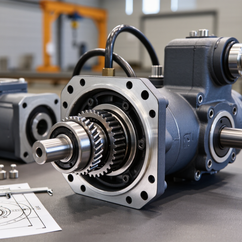
| Hydraulic Motor | Converts hydraulic flow and pressure into rotary motion for the planetary reduction stage. | Displacement: approximately 8–80 cm³/rev for compact track and wheel-drive units; speed commonly 20–300 rpm after reduction. | 80–350 bar
Continuous and peak ratings vary by motor design. | High starting torque, reversible rotation, and controllable speed through hydraulic flow. | Mini excavators, tracked carriers, compact drilling equipment, access platforms, and small agricultural machines. | Match displacement, rated pressure, flow requirement, shaft configuration, and mounting interface with the hydraulic circuit. |
| Planetary Gear Set | Reduces motor speed while multiplying torque in a compact and coaxial arrangement. | Typical reduction ratios: 4:1–100:1, often achieved with one to three planetary stages. | Indirectly exposed to hydraulic pressure through motor-generated torque; gear rating must exceed the required output load. | High torque density, balanced load distribution, and compact packaging. | Final drives, winches, slewing mechanisms, conveyors, and compact mobile machinery. | Check ratio, allowable radial load, peak torque, shock-load capacity, gear material, and heat-treatment method. |
| Sun Gear | Transfers input torque from the hydraulic motor into the planetary gears. | Usually manufactured from alloy steel with hardened or carburized tooth surfaces. | Not pressure-rated independently; torque capacity is determined by gear geometry and material strength. | Influences starting torque capacity, noise level, and overall gear-train durability. | All planetary final-drive assemblies. | Confirm tooth profile, surface hardness, backlash control, and compatibility with the motor output shaft. |
| Planet Gears and Carrier | Share transmitted torque across multiple gears and deliver reduced-speed output through the carrier. | Commonly three or four planet gears per stage; forged or machined steel carriers are widely used. | Torque and bearing loads increase as hydraulic pressure and motor displacement rise. | Improves load sharing and enables a shorter, higher-capacity drive package. | Track drives, compact wheel drives, crawler equipment, and low-speed hydraulic power units. | Evaluate planet-pin diameter, bearing support, carrier stiffness, load sharing, and serviceability. |
| Ring Gear | Provides the internal gear teeth that guide the planetary gears and complete the reduction stage. | Typically uses internal spur or helical teeth; housing-integrated or separately mounted designs are common. | Pressure is converted into mechanical tooth load through the motor and reduction stages. | Controls gear-stage strength, noise, efficiency, and housing compactness. | Compact final drives, crawler undercarriages, and hydraulic travel systems. | Inspect internal tooth hardness, concentricity, mounting accuracy, and resistance to impact loading. |
| Output Shaft or Hub | Transmits final reduced torque to a sprocket, wheel hub, drum, or other driven component. | Output speed commonly 10–150 rpm; torque may range from approximately 500 to 20,000 N·m in mini and compact equipment. | Mechanical output is governed by motor displacement, pressure differential, gear ratio, and efficiency. | Low speed with high usable torque and controlled directional operation. | Rubber tracks, steel tracks, wheels, augers, winch drums, and compact conveyors. | Specify shaft or flange dimensions, bolt pattern, maximum radial and axial loads, and required brake interface. |
| Multi-Disc Parking Brake | Holds the machine when hydraulic pressure is removed and may provide emergency stopping depending on system design. | Usually spring-applied and hydraulically released; holding capacity depends on disc count and friction design. | Release pressure is commonly much lower than the main motor working pressure, often around 15–35 bar. | Fail-safe holding function during parking, transport, or hydraulic power loss. | Mini excavators, tracked carriers, aerial work platforms, and mobile drilling machines. | Confirm static holding torque, release pressure, brake-release circuit, residual pressure limits, and thermal requirements. |
| Housing, Bearings, and Seals | Supports rotating components, retains lubricant, protects the gear train, and resists external contamination. | Common housing materials include ductile iron or high-strength cast steel; oil-bath lubrication is widely used. | Hydraulic ports and internal seals must withstand the specified motor pressure and case-drain conditions. | Determines leakage resistance, bearing life, heat dissipation, and protection from water or dust. | Outdoor construction, mining support, agricultural, forestry, and material-handling equipment. | Check sealing arrangement, ingress protection, bearing rating, lubricant specification, drain-port position, and operating temperature. |
| Hydraulic Circuit Requirements | Supplies clean hydraulic oil at the required flow and pressure while managing direction, braking, and case drainage. | Filtration commonly targets approximately ISO 4406 18/16/13 or cleaner, subject to the motor manufacturer’s specification. | System operating range may be 80–350 bar; relief-valve settings must protect the complete drive. | Flow controls speed; pressure differential controls available torque. | Open-circuit and closed-circuit mobile hydraulic systems. | Verify pump flow, relief settings, return-line back pressure, oil viscosity, filtration, flushing procedure, and hose sizing. |
| Performance and Efficiency | Describes how effectively hydraulic input is converted into mechanical output under operating load. | Overall mechanical-hydraulic efficiency is commonly about 65–90%, depending on speed, pressure, ratio, temperature, and wear. | Higher pressure can increase torque but also raises heat generation and component stress. | Actual output torque is lower than theoretical torque because of volumetric, mechanical, and gear losses. | Duty-cycle-sensitive mobile equipment and compact industrial machinery. | Use continuous and intermittent ratings separately; allow margin for shock loads, incline operation, and high ambient temperature. |
| Maintenance and Installation | Preserves gear, bearing, seal, and motor life throughout the service interval. | Typical checks include oil level, leakage, mounting bolts, hose condition, contamination, and operating temperature. | Depressurize the hydraulic system before installation, removal, inspection, or hose maintenance. | Correct alignment and clean oil reduce noise, heat, wear, and premature failure. | All mobile and compact hydraulic-drive equipment. | Follow the specified oil grade, break-in procedure, tightening torque, flushing method, storage conditions, and replacement interval. |



 Close