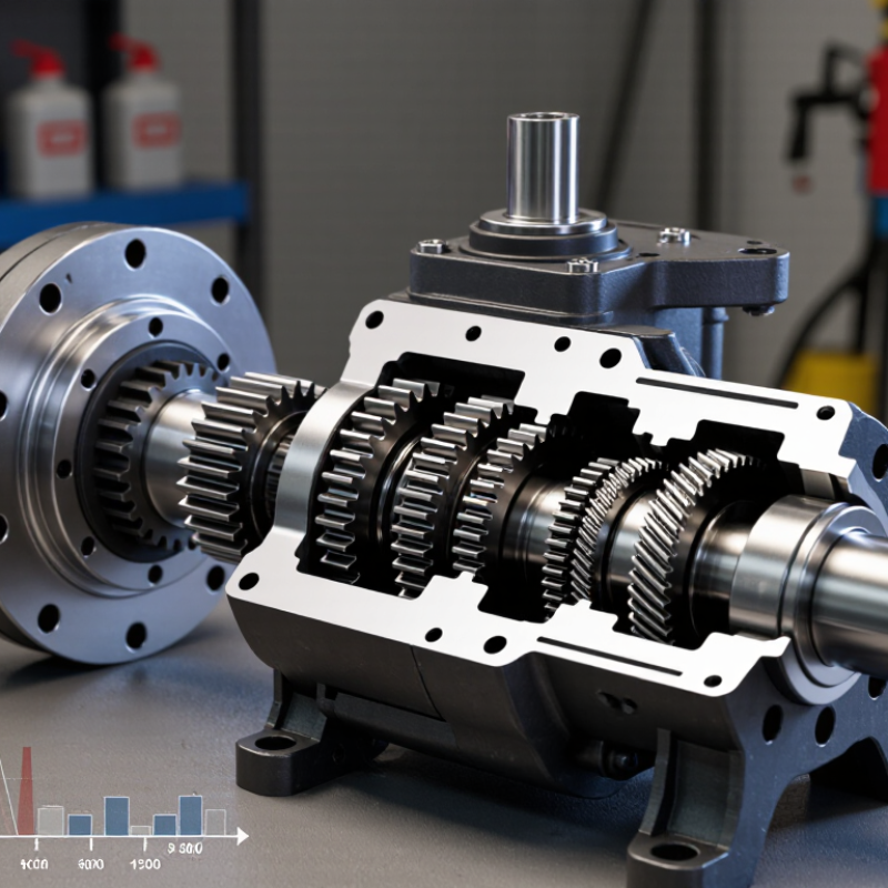
| Core construction | An inner rotor with external teeth turns inside an outer rotor with internal teeth. The two rotors are typically eccentric to one another and rotate within a close-fitting housing. | Check the pump’s construction drawing and mounting arrangement to confirm it fits the system and drive. |
| How it moves fluid | As the rotors turn, expanding spaces between the teeth draw fluid in; the fluid is carried around the housing and displaced as the spaces shrink. | Confirm the specified direction of rotation and inlet and outlet ports before installation. |
| Tooth-separation design | Many internal gear pumps use a crescent-shaped separator between the rotors. Gerotor-style designs use a different rotor arrangement and generally do not use a separate crescent. | Compare the actual design and performance data rather than assuming all internal gear pumps have identical construction. |
| Displacement and flow | Most hydraulic internal gear pumps are fixed-displacement units. Theoretical flow is displacement × rotational speed; in L/min, Q = displacement (cm³/rev) × speed (rpm) ÷ 1,000. | Allow for volumetric losses when estimating delivered flow. Use the manufacturer’s flow curves at the intended pressure, speed, and oil viscosity. |
| Pressure capability | Pressure is created by the system’s resistance to flow; the pump must be rated for the required continuous and peak operating pressures. | Compare continuous and intermittent pressure ratings, and ensure the system has correctly sized pressure protection. Do not select by a maximum-pressure figure alone. |
| Fluid and viscosity | Performance, lubrication, leakage, and starting behavior depend on the hydraulic fluid, its viscosity, and operating temperature. | Verify the permitted viscosity and temperature range for both cold starts and normal operation. Use fluid compatible with the pump’s seals and materials. |
| Noise and flow behavior | Internal gear pumps are commonly selected for relatively smooth flow and quiet operation, but actual noise and pulsation vary with design, speed, pressure, and installation. | For noise-sensitive systems, compare measured sound data under conditions similar to the application and check inlet piping for restrictions or aeration. |
| Inlet conditions | The inlet must supply fluid without excessive restriction, air entrainment, or cavitation. Poor inlet conditions can reduce performance and damage the pump. | Check the required inlet pressure or vacuum limits, fluid level, line size, filter arrangement, and suction-line layout. |
| Efficiency and heat | Mechanical and volumetric losses convert some input power into heat. Efficiency changes with operating pressure, speed, and fluid condition. | Use performance data at the actual duty point and consider the system’s cooling capacity and expected operating cycle. |
| What “best” means | There is no single best pump for every application; suitability depends on flow, pressure, speed, fluid, temperature, duty cycle, space, and service requirements. | Best choice: a pump whose published ratings cover the full operating envelope, with suitable inlet conditions, compatible fluid and seals, and adequate installation support. |



 Close