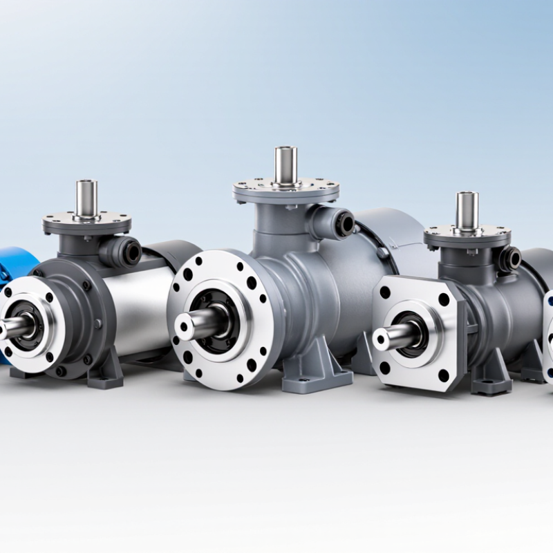
| Axial-piston, variable displacement | Applications requiring adjustable flow and pressure compensation or other control options. | Match any valve or manifold mounted on the pump assembly to its stated ISO 4401 size and port pattern. The pump porting itself is not defined by ISO 4401. | Confirm flange style, pilot diameter, bolt pattern, and port positions from the pump drawing. | Record shaft-end type, major diameter, usable length, and key or spline details; these are model-specific. | Compare displacement, pressure rating, control arrangement, rotation, and the complete mounting drawing. |
| Axial-piston, fixed displacement | Systems needing a fixed displacement per revolution, subject to the selected model’s operating limits. | Check the ISO 4401 interface only for associated control valves or manifold-mounted components; verify the stated interface size on their drawings. | Verify flange standard, register dimensions, bolt locations, and sealing arrangement against the existing drive or housing. | Confirm shaft diameter, projection length, keyway or spline form, and coupling engagement length from the manufacturer’s dimensional drawing. | Check flow at operating speed, pressure limits, fluid compatibility, and rotation direction. |
| External-gear | Commonly used for straightforward fixed-displacement hydraulic circuits. | ISO 4401 applies to a valve mounting face, if present—not to the gear pump’s inlet and outlet ports. | Check mounting flange, pilot/register, fastener pattern, and port orientation; do not assume a visually similar body is interchangeable. | Measure or verify shaft-end style, diameter, length, and key or spline dimensions using the exact pump drawing. | Compare displacement, speed range, pressure rating, port thread or flange type, and shaft compatibility. |
| Internal-gear | A fixed-displacement option for circuits where the selected model’s flow and pressure characteristics are suitable. | If a control valve is mounted on a manifold, verify that valve’s ISO 4401 pattern separately from the pump connections. | Confirm overall envelope, flange and pilot dimensions, bolt pattern, and inlet/outlet positions from the certified drawing. | Check the drive shaft’s diameter, extension, key or spline geometry, and permitted radial and axial loads. | Verify operating range, viscosity limits, fluid cleanliness requirements, and drive-coupling fit. |
| Balanced-vane | A fixed-displacement option used in systems where its specified flow, pressure, and fluid conditions meet the application needs. | Treat ISO 4401 as a valve/manifold interface requirement; it does not establish vane-pump mounting or shaft dimensions. | Match the pump’s flange, pilot, bolt pattern, and port arrangement to the installation drawing. | Verify shaft diameter, usable shaft length, key or spline specification, and coupling engagement before installation. | Confirm rated operating conditions, rotation, port connections, and the required filtration and fluid specifications. |



 Close