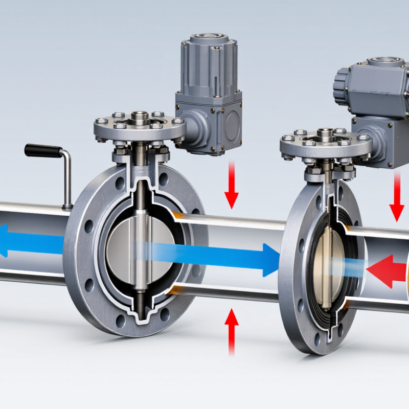
| Basic Definition | Valve type | A butterfly valve is a quarter-turn rotary valve used to start, stop, or regulate fluid flow. | A 90-degree rotation moves the valve between its main open and closed positions. |
| Main closure element | A circular disc mounted inside the flow passage. | The disc changes the available flow area as it rotates. |
| Typical movement | The disc rotates around a shaft or stem. | The movement is compact and requires less space than many multi-turn valve designs. |
| Primary flow paths | The valve may be installed in liquid, gas, or slurry piping when the selected design is suitable for the service. | Media compatibility depends on the body, disc, shaft, seat, pressure, temperature, and fluid properties. |
| Common body styles | Wafer, lug, flanged, and double-flanged configurations are commonly used. | The connection style determines how the valve is positioned and secured between or to pipe flanges. |
| Control function | Butterfly valves can provide isolation or throttling, depending on their design and service requirements. | Frequent throttling should only be performed when the valve is rated for control duty. |
| Sealing method | A resilient seat or a metal-seated arrangement forms the shutoff interface. | The seat material and design influence leakage performance, temperature capability, and chemical compatibility. |
| Actuation options | Manual handles, gear operators, pneumatic actuators, electric actuators, and hydraulic actuators may be used. | The actuator must provide enough torque for the operating pressure, seat friction, and safety requirements. |
| Operating Sequence | Step 1: Closed position | The disc is positioned across the pipe bore. | The disc and seat restrict the passage and provide shutoff when the valve is correctly selected and installed. |
| Step 2: Input from operator | A hand lever, gearbox, or actuator applies rotational force to the stem. | The applied torque overcomes resistance from the seat, disc, shaft, and differential pressure. |
| Step 3: Stem rotation | The stem transfers the turning force to the disc. | The disc rotates about its shaft axis rather than moving linearly along the pipe. |
| Step 4: Opening begins | As the disc turns away from the crosswise position, the flow area increases. | Fluid flow usually increases as the disc angle opens, although the relationship is not perfectly linear. |
| Step 5: Intermediate position | The disc is partly rotated across the bore. | The partial opening creates a restriction and can be used for flow control when permitted by the valve design. |
| Step 6: Fully open position | The disc is rotated approximately 90 degrees from the closed position and lies broadly parallel to the flow. | The passage is at or near its maximum effective area, minimizing the valve's flow restriction for that installation. |
| Step 7: Closing | The actuator reverses the stem rotation until the disc returns to the seat. | The seat contacts the disc perimeter and limits or stops flow, subject to the valve's specified shutoff performance. |
| Performance Factors | Pressure drop | The disc remains in the flow path even when open. | This can create more pressure loss than a full-bore valve with an unobstructed passage. |
| Flow control behavior | Flow changes with disc angle, pressure differential, and fluid properties. | A valve characteristic curve should be used when accurate modulation is required. |
| Torque requirement | Torque is affected by valve size, pressure differential, seat friction, temperature, and media. | Actuator sizing should use the manufacturer's certified torque data for the specific valve construction. |
| Installation alignment | The disc needs adequate clearance inside the pipe and must not strike adjacent components. | Incorrect alignment can damage the disc or seat and may prevent full opening or closing. |
| Temperature limit | The allowable temperature is determined largely by the seat, seals, body, and disc materials. | The published pressure-temperature rating must be checked before operation. |
| Maintenance focus | Inspection commonly includes the seat, disc edge, shaft, actuator, fasteners, and external leakage points. | Periodic functional checks help confirm that the valve reaches both defined end positions. |
| Safety requirement | The line should be isolated and depressurized before maintenance or disassembly. | Lockout and tagout procedures should be followed because stored pressure and automatic actuators can create hazards. |



 Close