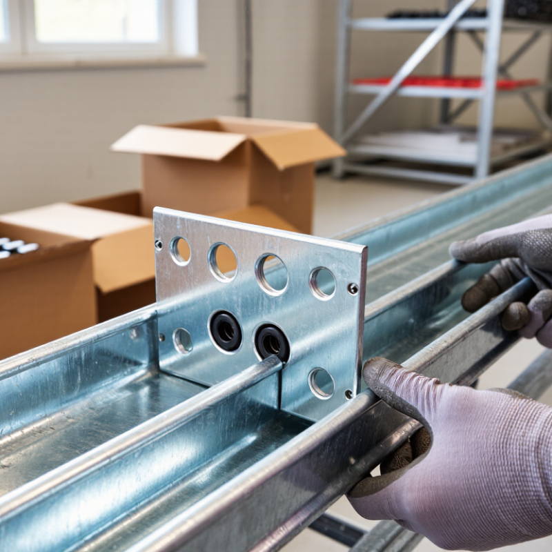
| 1. Match the joint to the tray construction | Ladder tray, with side rails and rungs | Straight splice plates; horizontal or vertical adjustable connectors for direction changes | Check side-rail height, tray width, rail profile, hole pattern, and the connector’s stated tray series or dimensional range. | Do not assume a connector fits just because the tray width matches; rail shape and hole spacing can differ. |
| 2. Check the bottom style and attachment points | Perforated or ventilated-bottom tray | Compatible splice plates, bolted through the designated side or bottom connection points | Confirm the connector is designed for the tray’s side-rail height and available hole locations; ensure it does not obstruct required openings. | Request dimensioned drawings when the tray and connector come from different suppliers. |
| 3. Verify support and loading requirements | Solid-bottom tray | Straight splice plates and fittings specified for the tray system | Check the manufacturer’s installation instructions for splice placement, support locations, and any load limitations at joints. | A connector joins tray sections; it should not be treated as a substitute for required structural supports. |
| 4. Confirm the mesh profile and connection method | Wire-mesh or basket tray | System-specific couplers, splice kits, or approved clips | Compare wire diameter, mesh dimensions, tray width, side-wall height, and the specified joining method. | A bolted plate made for ladder tray is not automatically suitable for wire-mesh tray; follow the tray system’s instructions. |
| 5. Match fittings to the route change | Ladder, ventilated, or solid-bottom tray systems | Horizontal elbows, vertical elbows, tees, crosses, or reducers with compatible connectors | Check the bend direction, angle, inside or outside radius, tray width, side-rail height, and fitting entry dimensions. | Confirm whether the fitting is intended for a horizontal or vertical route change before ordering splice hardware. |
| 6. Match connector material and finish to the environment | Any tray type, including steel or aluminum systems | Connectors and fasteners with a compatible base material and corrosion-resistant finish | Consider indoor or outdoor exposure, moisture, chemicals, and contact between dissimilar metals; check project specifications for material requirements. | A finish suitable for one environment may not be suitable for another. Confirm coating and material details for both connector and tray. |
| 7. Check electrical continuity and installation details | Metal tray systems where bonding or grounding is required by the project | Bonding jumpers or listed bonding hardware, where specified | Verify continuity requirements against applicable electrical codes and project documents; confirm whether the joint hardware alone is accepted for bonding. | Do not assume every splice provides the required electrical continuity. Follow local code and the engineered installation requirements. |



 Close