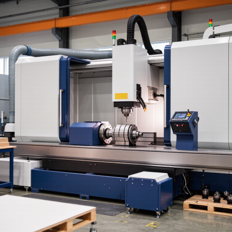
| CNC control architecture | Use a controller that supports coordinated multi-axis interpolation, tool offsets, work offsets, probing, and alarm diagnostics. | Confirm the number of controlled axes, simultaneous interpolation capability, program memory, USB/Ethernet transfer, and backup functions. | Side holes often require synchronized positioning, rotary indexing, or interpolation around a workpiece. Limited control functions can increase setup time and positioning errors. | Controller specification
Run a sample multi-axis program. | High |
| Control interface and usability | Prefer a clear HMI with tool-life monitoring, offset management, simulation, graphical alarms, and recovery procedures. | Assess display size, language options, access levels, program search, dry-run mode, single-block operation, and operator guidance. | Good interface design reduces incorrect offsets, restart mistakes, and operator training time, especially when drilling different hole orientations. | Live demonstration
Review operator manual. | Medium |
| Spindle speed and torque range | Select a spindle range suited to the workpiece material, drill diameter, and tooling system. | Check maximum speed, rated power, continuous torque, speed control resolution, and the usable low-speed torque range. | Small carbide drills need higher cutting speeds, while larger drills and difficult materials need sufficient torque. A high maximum rpm alone does not guarantee suitable cutting performance. | Load test
Compare speed-torque curve with tooling data. | High |
| Toolholding system | Use a rigid, balanced holder compatible with the drill diameter and required runout target. | Record holder type, clamping range, balance grade if specified, allowable speed, and gauge-length limits. | Toolholder accuracy and clamping stability directly affect hole position, tool life, surface finish, and total indicated runout at the tool tip. | Measure with a test arbor
Check holder certificates. | High |
| Runout requirement | For a ≤0.01 mm runout target, define the measurement location, gauge force, spindle condition, toolholder, and tool projection. | Specify TIR at the holder taper, gauge line, or cutting-tool tip. A practical acceptance check should state the exact measurement point and tolerance. | Runout increases uneven cutting load and hole oversize. The machine spindle, holder, collet, tool, and setup all contribute to the final result. | Dial indicator or electronic tester
Measure at a defined gauge length. | Critical |
| Spindle and axis repeatability | Require documented positioning accuracy and repeatability appropriate to the hole-location tolerance. | Review axis repeatability, backlash compensation, thermal compensation, spindle radial/axial runout, and inspection conditions. | Low tool runout cannot compensate for poor axis repeatability, thermal drift, backlash, or an unstable machine structure. | Laser, ball-bar, or calibrated indicator test | Critical |
| Chip evacuation | Provide through-tool coolant, external coolant, air blast, or a combination suitable for hole depth and material. | Check coolant pressure and flow, filtration, tank capacity, chip conveyor or tray design, and access for cleaning. | Effective chip removal reduces recutting, drill jamming, heat buildup, burr formation, and premature tool failure. | Drilling trial
Inspect chips, hole walls, and coolant flow. | High |
| Deep-hole capability | Match the machine and tooling strategy to the hole-depth-to-diameter ratio. | Document maximum recommended depth, peck-cycle functions, retract distance, dwell control, and coolant delivery at the cutting edge. | As depth increases, chip packing and heat removal become more difficult. Peck drilling and reliable chip evacuation may be necessary. | Test the target depth-to-diameter ratio | High |
| Coolant and filtration | Use clean coolant with filtration suitable for the process and tool size. | Check filtration rating, tank volume, pump flow, nozzle positioning, leak control, and coolant concentration monitoring. | Fine chips and contaminated coolant can damage pumps, obstruct nozzles, scratch finished surfaces, and reduce drilling consistency. | Inspect filtration system
Measure flow at the tool area. | Medium |
| Workholding and access | Ensure rigid clamping and unobstructed access to every required side-hole position. | Evaluate fixture stiffness, datum repeatability, clamping clearance, part support, rotary-table capacity, and collision margins. | Side drilling can introduce lateral cutting forces and tool deflection. Poor support may cause vibration, position errors, or part movement. | Fixture trial
Check clamping deformation. | High |
| Machine rigidity and vibration control | Choose a rigid machine structure with adequate guideways, spindle support, and foundation requirements. | Review machine mass, spindle bearing arrangement, guideway type, maximum tool overhang, and recommended cutting conditions. | Vibration negatively affects hole roundness, surface finish, tool life, and dimensional stability, particularly with long side-hole tools. | Cutting trial
Monitor sound, vibration, and surface finish. | High |
| CE compliance for EU use | For equipment placed on the European market, request the applicable EU Declaration of Conformity and technical documentation. | Check machinery safety assessment, electrical safety, EMC compliance, guarding, emergency stops, interlocks, instructions, and the CE marking. | CE marking is a conformity declaration by the manufacturer or responsible economic operator; it is not a substitute for checking the actual safety functions and documentation. | Review signed declaration
Inspect the machine and safety circuits. | Critical |
| Guarding and interlocks | Require enclosed moving parts, interlocked access doors, emergency stops, and prevention of unexpected restart. | Inspect door-locking devices, safety switches, emergency-stop response, chip containment, visibility, and access during setup mode. | Side-hole drilling creates rotating-tool, flying-chip, coolant, and entanglement hazards. Safety functions must remain effective in normal and setup operation. | Functional safety test
Review risk assessment. | Critical |
| Programming and drilling cycles | Confirm fixed cycles for drilling, peck drilling, tapping, dwell, retract, and safe-plane control. | Check support for canned cycles, coordinate rotation, polar or cylindrical interpolation where required, tool-radius compensation, and probing routines. | Suitable cycles help control chip load, reduce programming errors, and maintain consistent results across multiple side-hole locations. | Program validation
Run simulation and dry cycle. | High |
| Measurement and inspection | Define acceptance checks for hole diameter, location, perpendicularity, roundness, depth, and runout. | Identify gauges and instruments such as plug gauges, bore gauges, CMM, dial indicators, and calibrated test bars. | Measurement results are meaningful only when the datum system, temperature, gauge method, and inspection uncertainty are controlled. | Inspection plan
Use calibrated equipment. | Critical |
| Thermal stability | Assess warm-up procedures and compensation when tight tolerances are required. | Review spindle warm-up cycle, coolant temperature control, ambient-temperature range, and documented thermal drift behavior. | Spindle and machine temperature changes can alter tool position and hole location, even when static runout is within specification. | Repeat measurements after warm-up | Medium |
| Maintenance and serviceability | Prefer accessible lubrication points, clear maintenance intervals, spare-part availability, and diagnostic support. | Check lubrication monitoring, coolant-cleaning access, filter replacement procedure, alarm history, backup method, and service response capability. | Consistent accuracy depends on clean coolant, correct lubrication, stable tooling, and timely correction of spindle or axis problems. | Review maintenance schedule
Inspect service access. | Medium |
| Acceptance testing before purchase | Require a documented factory or site acceptance test using the intended material, tool, fixture, coolant, and hole pattern. | Record runout, hole diameter, hole location, cycle time, chip evacuation performance, alarms, and repeatability over multiple parts. | A realistic test reveals the combined effect of the machine, tooling, workholding, cutting data, and operator procedure better than individual specifications. | Signed acceptance report | Critical |
| Overall purchase decision | Choose the machine only when control capability, safety documentation, chip evacuation, workholding, and measured accuracy meet the process requirement together. | Use a weighted scorecard: safety and compliance first, then measured accuracy, process capability, reliability, serviceability, and total operating cost. | A low purchase price or high spindle speed cannot offset inadequate safety, unstable runout, poor chip control, or insufficient axis capability. | Pass / Conditional / Fail
Document all open risks. | Critical |



 Close
Close