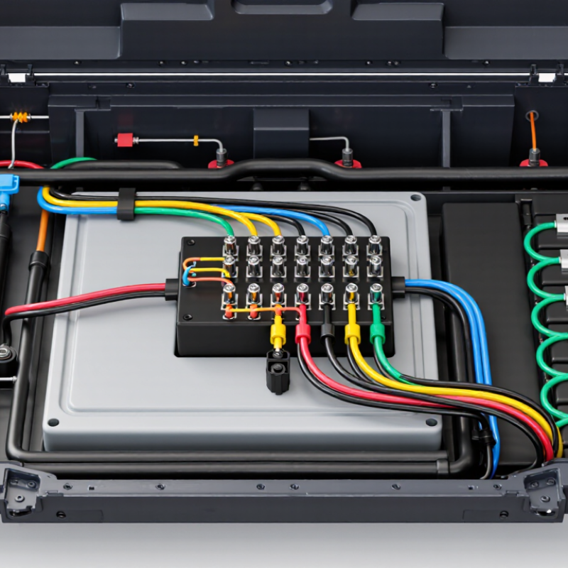
| Electrical Architecture | Number of cells, sensing channels, balancing circuits, service loops, and auxiliary power lines. | Cell-monitoring circuits commonly use low-current measurement conductors, while balancing circuits may carry approximately 50–300 mA depending on the BMS design. | Review the wiring diagram, pinout, connector keying, and circuit separation. | Pass Every circuit has a defined function, pin assignment, protection strategy, and diagnostic path. |
| Conductor Selection | Current, allowable voltage drop, conductor length, temperature, insulation system, and routing conditions. | Use the conductor cross-sectional area and insulation rating calculated for the actual load and environment. For a 1.5 m one-way copper circuit, remember that voltage-drop calculations use approximately 3.0 m of total circuit length. | Perform resistance, voltage-drop, and thermal calculations at the maximum continuous and peak load. | Pass Voltage drop and conductor temperature remain within the project limits at the worst-case operating condition. |
| Signal Integrity | Measurement accuracy, noise exposure, shielding requirements, and separation from high-current switching paths. | Keep cell-sense wires twisted or routed consistently where required, minimize unintentional loop area, and separate sensitive measurement lines from high-current conductors. | Check resistance balance, continuity, induced-noise susceptibility, and measurement deviation under switching loads. | Pass No intermittent open circuit, unacceptable measurement offset, or communication disturbance is observed. |
| Crimp and Terminal Quality | Terminal size, wire gauge range, crimp geometry, pull-out strength, and contact resistance. | Crimp dimensions and pull-force limits must come from the selected terminal and wire combination; they are not universal values. | Use crimp-height inspection, cross-section analysis, terminal pull testing, and millivolt-drop measurement. | Pass Crimps meet the terminal supplier's validated specification, with no broken strands, bell-mouth defect, or excessive contact resistance. |
| ISO 26262 Alignment | Safety goals, ASIL allocation, fault reactions, and the harness contribution to the safety concept. | Analyze harness faults such as open circuit, short to ground, short between adjacent circuits, reversed connection, and increased contact resistance. | Document the harness interface in the HARA, functional safety concept, technical safety concept, and safety analysis as applicable. | Pass Safety-related faults have defined detection, mitigation, or controlled-failure behavior. ISO 26262 does not independently certify a wire harness. |
| LV 214 Interface Validation | Connector mating, terminal retention, mechanical loading, electrical performance, and environmental exposure. | LV 214 is commonly used as an automotive connector testing reference; exact severities and acceptance limits depend on the connector and project specification. | Apply the relevant LV 214-based sequence for contact resistance, vibration, temperature cycling, humidity, mechanical abuse, and terminal retention. | Pass The connector remains mated, terminals remain retained, and electrical performance stays within the approved component specification. |
| Mating Durability | Serviceability requirements, connector access, latch design, and expected maintenance events. | Automotive connector mating ratings vary by design; 1,000 mating cycles should be treated as a demanding, project-defined durability target rather than a universal LV 214 requirement. | Mate and unmate the complete harness assembly for 1,000 cycles using controlled alignment, speed, and insertion force. | Pass No latch failure, terminal back-out, seal damage, abnormal insertion-force increase, or unacceptable contact-resistance rise occurs. |
| Environmental Durability | Temperature range, humidity, condensation, salt exposure, fluids, vibration, and mechanical strain. | Define the vehicle installation zone and use the applicable environmental profile; a typical development envelope may include approximately −40°C to +125°C, subject to the vehicle design. | Combine temperature cycling, damp heat, vibration, fluid exposure, and post-test electrical inspection. | Pass No insulation cracking, seal leakage, corrosion that affects function, chafing, or intermittent electrical fault is detected. |
| Insulation and Isolation | Insulation material, creepage, clearance, dielectric withstand, and isolation-monitoring strategy. | Test voltage and insulation-resistance limits must be specified by the battery-pack electrical architecture and applicable component requirements. | Perform continuity, insulation resistance, dielectric withstand where applicable, and isolation checks before and after environmental tests. | Pass Measured values remain above the project-defined minimum, with no dielectric breakdown or unintended conduction path. |
| Mechanical Routing | Bend radius, clamp spacing, abrasion points, connector strain relief, and tolerance stack-up. | Maintain the cable manufacturer's minimum bend radius and prevent the connector from carrying continuous wire tension or sharp-edge contact. | Inspect the installed routing and conduct vibration, flex, abrasion, and pull-strain testing under representative assembly conditions. | Pass No conductor fatigue, terminal movement, insulation wear-through, clip release, or connector load-transfer failure is found. |
| Production Traceability | Crimp tooling, inspection frequency, test coverage, repair controls, and end-of-line verification. | Record wire batch, terminal lot, tooling identification, crimp measurements, continuity results, and operator or machine traceability. | Use 100% continuity and short-circuit testing, supported by periodic crimp cross-sections and pull-force audits. | Pass Each harness has a retrievable quality record and no unapproved splice, terminal, wire, or repair is present. |



 Close