| System Voltage | Confirm the arrester is suitable for the system line-to-line voltage and grounding arrangement. | Rated voltage and continuous operating voltage must be compatible with the highest continuous system voltage. | Compare the nameplate and technical documentation with the power-system design data. | During design, procurement, and replacement. | Prevents overheating and premature failure caused by continuous overvoltage. |
| MCOV / Uc | Check the maximum continuous operating voltage rating. | The selected Uc should be equal to or greater than the maximum continuous voltage applied across the arrester. | Review the nameplate, system neutral conditions, and temporary overvoltage study. | Before installation and after system-voltage changes. | Correct MCOV selection is essential for thermal stability. |
| Nominal Discharge Current | Select the appropriate nominal discharge current for the installation category and exposure level. | Common distribution-class values include 5 kA and 10 kA, depending on the applicable standard and system duty. | Use the lightning exposure, network configuration, and applicable utility or project specification. | At product selection and network modification. | Indicates the arrester's standardized current-duty classification; it is not the only measure of energy capability. |
| Lightning and Switching Energy | Verify that the arrester can withstand the expected surge energy and temporary overvoltages. | Review line-discharge class, energy capability, temporary-overvoltage withstand, and pressure-relief performance. | Check certified type-test results and the system insulation-coordination study. | During engineering and design changes. | Reduces the risk of thermal runaway or mechanical rupture during severe surges. |
| Protective Level | Compare the residual voltage with the insulation withstand level of the protected equipment. | The arrester protection level should provide adequate margin below the equipment lightning impulse withstand level. | Perform insulation-coordination calculations using manufacturer test data and actual lead lengths. | During design, commissioning, and major layout changes. | Confirms that the arrester limits surge voltage before it reaches the equipment. |
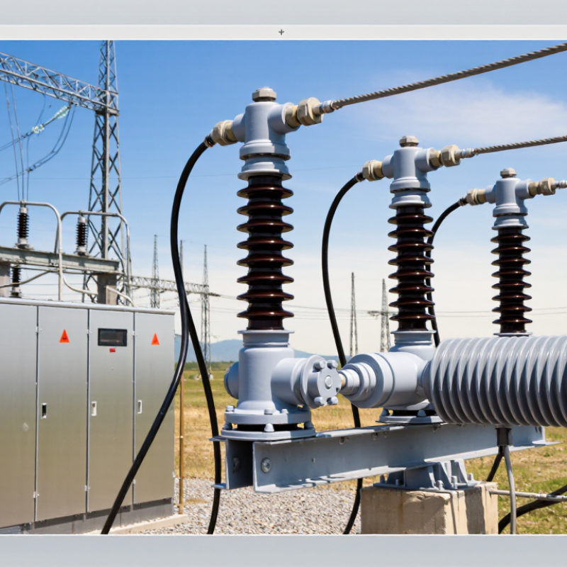
| Polymer Housing | Inspect the silicone-rubber housing, sheds, seals, and bonding interfaces. | No cracks, punctures, tracking, erosion, loose sheds, contamination damage, or visible seal deterioration. | Visual inspection from a safe distance; use close inspection during an outage when required. | At commissioning and at least annually; more often in severe pollution or coastal environments. | The housing provides insulation, weather protection, and resistance to contamination and moisture. |
| Installation Location | Install the arrester as close as practical to the equipment being protected. | Avoid unnecessary conductor length, sharp bends, and routing that increases inductive voltage. | Review the physical layout and measure conductor routing during commissioning. | During installation and after equipment relocation. | Short, direct connections improve the effective protection level. |
| Lead Length and Routing | Check that line and ground leads are short, straight, and separated from sensitive circuits. | Do not coil excess conductor; avoid tight loops and unnecessary bends. | Physical inspection against the approved installation drawing. | At installation, commissioning, and maintenance outages. | Reduces additional voltage produced by lead inductance during fast transients. |
| Grounding and Bonding | Verify the arrester ground connection is secure, corrosion-free, and bonded to the station or equipment grounding system. | The grounding path should be low impedance, mechanically robust, and consistent with the site grounding design. | Inspect connections, check torque according to the installation instructions, and test continuity where appropriate. | At commissioning and during scheduled outages. | A poor ground path can greatly increase the voltage appearing at protected equipment. |
| Mechanical Installation | Check mounting hardware, terminal connections, clearances, and mechanical loading. | Hardware must be tight and compatible with the arrester design; do not exceed specified bending or cantilever loads. | Visual inspection and torque verification using approved procedures. | At installation and after severe weather or maintenance work. | Prevents mechanical damage, loose connections, and flashover caused by inadequate clearance. |
| Contamination and Environment | Assess salt, dust, industrial pollution, ultraviolet exposure, altitude, humidity, and temperature. | Housing creepage distance and environmental rating should match the site severity. | Compare site conditions with the product environmental specifications and inspect contamination patterns. | At design stage and during periodic inspections. | Suitable creepage and weather resistance reduce surface leakage and tracking risk. |
| Leakage Current Monitoring | Trend total leakage current or third-harmonic resistive current where suitable monitoring equipment is available. | Use the installed arrester's baseline and manufacturer guidance; a rising trend is more significant than one isolated reading. | Use calibrated online monitoring equipment under comparable voltage and environmental conditions. | Periodically, with increased frequency for critical assets or abnormal trends. | Trend analysis may identify moisture ingress, aging, or deterioration before failure. |
| Thermal Inspection | Look for abnormal temperature differences between phases or compared with historical images. | Interpret results together with load current, ambient conditions, contamination, and connection condition. | Use infrared thermography by qualified personnel under suitable load conditions. | During planned inspections or when leakage-current trends change. | A persistent thermal anomaly can indicate electrical or connection problems. |
| Surge Counter and Event Records | Record surge counts, discharge magnitude where available, and any pressure-relief or disconnector operation. | Investigate unusual frequency, high-current events, or any indication of arrester disconnector operation. | Inspect the counter and compare records with lightning, switching, and protection-system events. | Review after major storms, switching incidents, and scheduled maintenance. | Event history supports risk assessment and replacement decisions. |
| Standards and Type Testing | Confirm the design has been tested to the applicable surge-arrester standard. | Typical references include IEC 60099-4 or IEEE C62.11, subject to project requirements. | Request current type-test documentation, routine-test information, and quality records. | Before purchase and when the design or production configuration changes. | Independent, applicable testing demonstrates performance under standardized electrical and environmental duties. |
| Replacement Decision | Assess condition, trend data, service history, surge exposure, and any visible damage. | Replace immediately if there is cracking, severe tracking, major thermal abnormality, failed monitoring, or evidence of a protective operation. | Use a documented engineering assessment; do not rely on age alone. | After abnormal events and during asset-life reviews. | Condition-based decisions reduce both unexpected failures and unnecessary replacement. |



 Close
Close