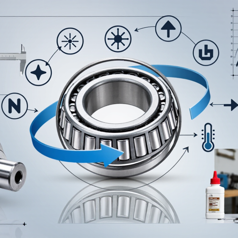
| Basic Construction | A tapered roller bearing consists of an inner ring, outer ring, tapered rollers, and a cage. | The conical geometry allows the rolling elements and raceways to share a common apex when extended. | Confirm that the complete cup-and-cone assembly is compatible; the inner ring and rollers are commonly supplied as one assembly, while the outer ring is separate. |
| Primary Load Capability | Designed to support combined radial loads and axial loads in one direction. | Load capacity is created by the line contact between the tapered rollers and raceways. | Use a single bearing when the axial load direction is known. Use a matched pair or another opposed arrangement when axial loads can reverse. |
| Axial Load Direction | A single tapered bearing normally carries thrust in only one direction. | The roller-raceway geometry produces an axial force component that must be reacted by another bearing or locating feature. | For two-direction thrust, consider face-to-face, back-to-back, or tandem arrangements according to stiffness, space, and load requirements. |
| Contact Geometry | The rollers and raceways are tapered rather than cylindrical. | The taper converts part of the radial loading into an axial component and provides high combined-load capacity. | Choose the bearing angle and internal geometry from the required radial-to-axial load ratio, speed, stiffness, and adjustment method. |
| Radial Load | Well suited to moderate-to-heavy radial loads, subject to the bearing series and operating conditions. | Line contact gives a larger effective contact area than point-contact rolling elements under comparable conditions. | Check the basic dynamic load rating, basic static load rating, load spectrum, shock level, and required fatigue life. |
| Axial Load | Axial capacity increases with the effective contact angle, but the exact capacity depends on the complete bearing geometry. | A larger contact angle generally increases thrust-carrying ability while increasing the axial component generated by radial load. | Do not select by contact angle alone. Verify manufacturer-neutral load ratings, equivalent dynamic load, static safety, and bearing arrangement. |
| Bearing Arrangement | Common arrangements include single-row, paired, and multi-row configurations. | Arrangement controls axial load capacity, stiffness, preload, thermal behavior, and shaft location. | Use a single row for one-direction thrust; use opposed pairs or multi-row designs when higher stiffness or bidirectional thrust capacity is required. |
| Internal Clearance | Operating clearance is influenced by initial setting, mounting interference, temperature, elastic deflection, and lubrication. | Excessive clearance can reduce stiffness and cause impact loading; insufficient clearance can create overheating and premature damage. | Specify the required setting or preload method rather than selecting clearance in isolation. Account for shaft and housing thermal expansion. |
| Preload | Preload removes internal looseness and can improve rigidity and running accuracy. | Too much preload increases friction, heat generation, and power loss. | Apply preload only when the application requires increased stiffness, reduced deflection, or improved positioning. Validate temperature and torque during testing. |
| Speed Capability | Speed capability is affected by bearing size, cage design, lubrication, load, preload, and operating temperature. | Tapered roller bearings generally generate more sliding and heat than many comparable point-contact bearing designs. | Use the permissible-speed guidance for the selected geometry and lubricant. Reduce speed limits when preload, heavy load, or poor cooling is present. |
| Lubrication | Oil and grease are both used; oil generally provides better heat removal at high speed. | Lubrication separates contacting surfaces, removes heat, and protects against wear and corrosion. | Select lubricant viscosity and consistency based on speed, load, temperature, contamination, sealing, relubrication interval, and compatibility. |
| Operating Temperature | Temperature depends on speed, load, preload, lubricant, seals, ambient conditions, and heat dissipation. | High temperature can reduce lubricant life, alter internal setting, and accelerate material degradation. | Check dimensional changes caused by thermal expansion and use heat-resistant materials or lubricant when the application requires them. |
| Mounting Fit | The shaft and housing fits determine load-zone support, creep resistance, and internal setting after installation. | An incorrect interference fit can distort the rings or change the intended clearance. | Define shaft diameter, housing bore, tolerance class, roundness, shoulder geometry, and mounting method before final selection. |
| Adjustment Method | Axial adjustment is commonly used to establish endplay or preload in opposed tapered-bearing arrangements. | Correct adjustment controls stiffness, friction, temperature, and service life. | Follow a controlled setting procedure using measured torque, axial displacement, temperature, or endplay. Avoid relying only on nut position. |
| Static Load Safety | The basic static load rating is used to evaluate permanent deformation risk when the bearing is stationary or operating at very low speed. | Shock loads and vibration can produce indentations even when calculated fatigue life is adequate. | Check the static safety factor for peak loads, impact, oscillation, transport conditions, and standstill vibration. |
| Dynamic Bearing Life | For roller bearings, the commonly used basic rating-life relationship is L10 = (C/P)10/3 million revolutions. | L10 represents the life at which 90% of an identical group of bearings is expected to reach or exceed the calculated rating life under defined conditions. | Use the equivalent dynamic load P, dynamic load rating C, actual duty cycle, speed, lubrication, contamination, and reliability target in the calculation. |
| Contamination Control | Dirt, water, and abrasive particles can substantially reduce bearing life. | Contaminants damage raceways, rollers, and lubricant films and may initiate surface fatigue. | Use suitable seals, shields, labyrinths, clean assembly practices, filtered lubricant, and appropriate maintenance intervals. |
| Misalignment | Tapered roller bearings require controlled alignment between the shaft, housing, and raceways. | Misalignment creates uneven load distribution, edge stress, heat, and accelerated wear. | Control shaft and housing alignment, shoulder squareness, mounting runout, and structural deflection. |
| Material and Hardness | Bearing rings and rollers are normally manufactured from hardened bearing steel or application-specific high-performance materials. | Hardness, cleanliness, heat treatment, and surface finish affect fatigue resistance and wear performance. | For severe temperature, corrosion, electrical, or contamination conditions, evaluate special material or coating requirements separately. |
| Dimensional Compatibility | The essential dimensional references are bore diameter, outside diameter, total width, cup width, cone width, and shoulder dimensions. | These dimensions determine whether the bearing fits the shaft, housing, spacer, seal, and adjacent components. | Verify all boundary dimensions and interchange requirements from the applicable bearing specification or engineering drawing. |
| Cage Considerations | The cage maintains roller spacing and guides the rollers through the loaded and unloaded zones. | Cage design influences friction, lubricant distribution, speed capability, and resistance to vibration. | Select the cage type according to speed, load, temperature, lubrication, shock, and chemical compatibility. |
| Best-Fit Applications | Typical applications include wheel hubs, gearboxes, axles, transmissions, industrial reducers, and heavy rotating equipment. | These systems often combine substantial radial loading with controlled axial positioning. | Confirm the duty cycle, shock loading, reversing thrust, speed range, environment, maintenance plan, and available installation space. |
| Final Selection Checklist | Required inputs include load magnitude and direction, speed, life target, temperature, lubrication, fit, clearance or preload, contamination, and mounting arrangement. | A bearing that matches only the shaft diameter may still fail because of incorrect load direction, setting, lubrication, or operating temperature. | Compare calculated life, static safety, speed, thermal behavior, stiffness, serviceability, and total installed cost before approval. |



 Close