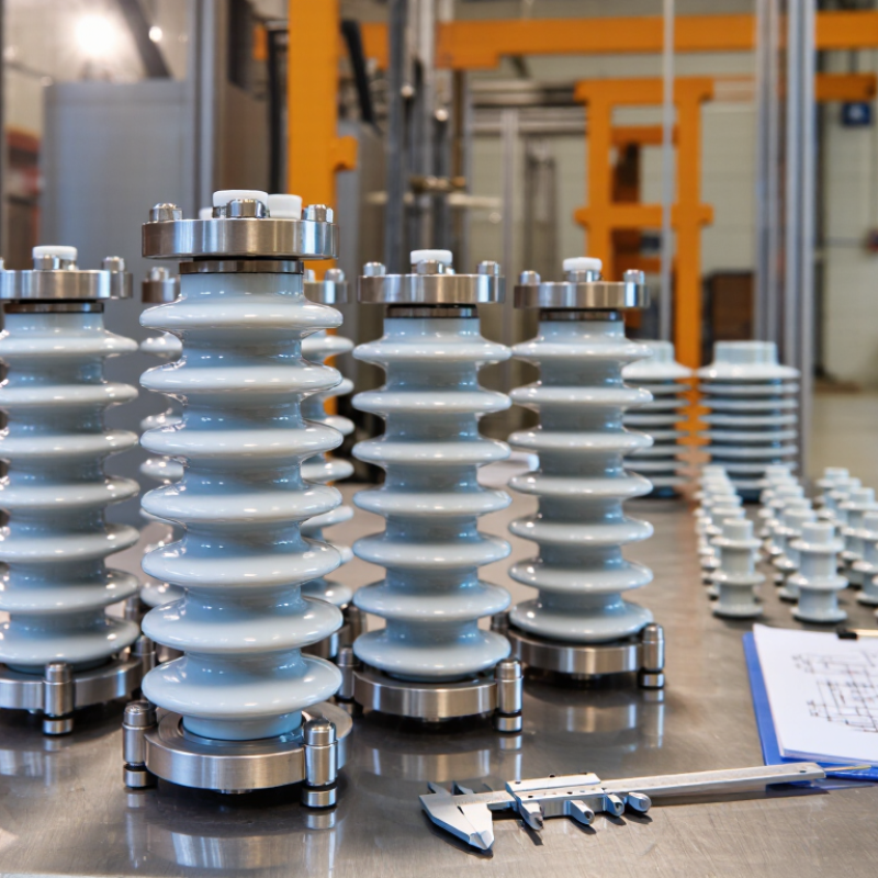
| Applicable standard | DIN 42530, subject to the exact edition and applicable national requirements | Request the supplier’s dimensional drawing and conformity documentation for the specified DIN 42530 configuration. | Confirm that the supplied bushing matches the transformer tank, cover thickness, terminal arrangement, and insulation system before installation. |
| Voltage class | 1 kV nominal voltage class | Specify the system’s highest operating voltage, insulation coordination, and required test levels rather than relying only on the nominal label. | Maintain the designed clearances and creepage distances. Do not operate above the approved voltage class. |
| Rated current | 250 A continuous current rating, commonly identified as 1/250 | Check continuous load current, overload profile, conductor size, connection hardware, and permissible temperature rise. | Tighten connections to the specified torque and inspect for discoloration, hot spots, oxidation, or looseness during service inspections. |
| Bushing construction | Porcelain insulator with a conductive current path and sealing components | Confirm porcelain profile, conductor material, terminal type, gasket material, and compatibility with the transformer fluid. | Handle porcelain carefully. Do not use a bushing with chips, cracks, damaged glaze, bent terminals, or degraded sealing surfaces. |
| Mounting arrangement | Tank or cover-mounted arrangement; exact hole pattern and dimensions must be confirmed from the approved drawing | Provide cover thickness, mounting-hole diameter, bolt-circle or hole spacing, internal projection, external projection, and terminal orientation. | Clean the mounting face, install the gasket evenly, and tighten fasteners in a crosswise sequence to prevent flange distortion. |
| Environmental conditions | Outdoor or indoor use according to the selected creepage, sealing, and enclosure requirements | State altitude, ambient temperature, pollution level, solar exposure, humidity, salt contamination, and installation orientation. | Keep the porcelain surface clean and dry. Increase inspection frequency in coastal, dusty, chemically aggressive, or high-condensation locations. |
| Transformer fluid compatibility | Compatibility with the specified insulating liquid and sealing materials | Identify the fluid type, operating temperature range, gasket compound, and any restrictions on oils or ester fluids. | Prevent contamination during installation and check for oil seepage around the flange, gasket, and terminal area. |
| Electrical clearances | Clearances must be based on the approved design, system voltage, and insulation coordination | Request internal and external clearance data and verify compatibility with busbars, leads, tank walls, and nearby grounded parts. | Do not route conductors close to grounded metal or sharp edges. Maintain the manufacturer’s minimum bending radius for connected cables. |
| Terminal connection | Connection hardware suitable for a 250 A continuous circuit | Confirm terminal dimensions, stud or palm configuration, conductor material, plating, and included nuts, washers, and locking devices. | Use compatible contact materials or approved joint compound where required. Apply the specified torque with a calibrated tool. |
| Factory documentation | Dimensional drawing, rating information, inspection record, and installation instructions | Require traceable documentation, packing identification, quantity, revision level, and certificates requested by the project specification. | Keep documents with the transformer maintenance records and verify the part number against the approved bill of materials. |
| Pre-installation inspection | Visual and dimensional inspection before fitting | Define the acceptance procedure for cracks, glaze defects, dimensions, terminal condition, gasket quality, and packaging damage. | Inspect under good lighting, remove dust with a clean lint-free cloth, and reject any component with structural porcelain damage. |
| Recommended commissioning checks | Connection integrity, insulation condition, leakage check, and functional verification | Agree on test scope with the transformer manufacturer and the responsible electrical engineer; test limits depend on the complete assembly. | Verify torque, grounding, oil level, absence of leaks, phase identification, and safe electrical clearances before energization. |
| Routine maintenance | Periodic visual, thermal, mechanical, and cleanliness inspections | Ask for recommended inspection intervals and spare-gasket or replacement-part availability. | Inspect at least during scheduled transformer maintenance and use infrared thermography on energized equipment where permitted. |
| Replacement criteria | Replace when structural, sealing, insulation, or thermal performance is no longer acceptable | Confirm interchangeability; a visually similar bushing may not have the same dimensions, creepage, current rating, or insulation level. | Replace after porcelain cracking, persistent leakage, severe tracking, terminal overheating, or irreversible corrosion. De-energize and isolate before work. |
| Supplier evaluation | Technical conformity, documentation quality, dimensional accuracy, lead time, and after-sales support | Compare approved drawings, delivery schedule, packaging method, warranty terms, inspection records, and response time for technical queries. | Select the supplier that can provide traceability and stable replacement availability, not only the lowest purchase price. |



 Close