| Precast element weight | Calculate the element’s self-weight from its dimensions and specified concrete density. Normal-weight concrete is commonly estimated at about 2,400 kg/m³, but use the project value. | Include any permanently attached items and account for temporary lifting inserts or other relevant loads. | Verify the calculated mass against drawings, production records, or an approved weight schedule. |
| Number and layout of anchors | Identify the planned anchor count, lifting points, and sling arrangement for each handling stage. | Do not assume that each anchor carries an equal share. Sling geometry, element flexibility, and uneven load sharing can increase individual anchor forces. | Check the actual load distribution and permitted lifting configuration against the anchor system’s technical documentation. |
| Anchor force and lifting angle | Determine the force at each anchor for the lift, including sling angle, dynamic effects, and any applicable load factors. | As sling legs become more horizontal, tension in each leg increases. Use the project’s lifting design method rather than the element weight alone. | Confirm that anchor and clutch capacities cover the calculated forces in the intended load direction. |
| Concrete strength at lifting | Establish the concrete compressive strength when the element will actually be lifted, not only its specified strength at a later age. | Use verified production or test data and the minimum strength required by the engineered anchor design. | Do not lift before the required concrete strength and curing conditions have been achieved. |
| Element thickness and edge distance | Check the available member thickness, anchor location, distance to edges, and spacing between anchors. | Thin or narrow elements may limit embedment and can increase the risk of concrete breakout or splitting. | Use the required embedment, edge distances, spacing, and reinforcement details from the approved design documentation. |
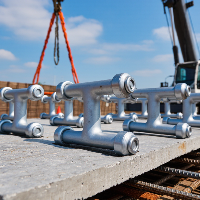
| Load direction and anchor orientation | Determine whether each anchor will be loaded in tension, shear, or an angled direction during stripping, turning, transport, or erection. | Dog bone anchors are embedded inserts; their suitability depends on the specific system, orientation, and approved loading directions. | Check permitted load directions and any restrictions for combined or angled loading in the system documentation. |
| Reinforcement and concrete breakout | Review reinforcement layout and the potential failure modes around the embedded anchor. | Designed local reinforcement may be needed to control splitting or support the load path; reinforcement must not conflict with anchor placement. | Coordinate anchor locations and reinforcement with shop drawings and the responsible structural engineer. |
| Lifting clutch compatibility | Confirm the lifting clutch or attachment is specifically compatible with the anchor head and rated for the required load. | Anchor and clutch systems are not automatically interchangeable, even when parts appear similar. | Inspect the clutch for damage and verify engagement, identification, and inspection status before use. |
| Handling stages | Assess every planned operation: demoulding, turning, storage, transport, and final erection. | The most demanding stage may not be the final lift. Suction, adhesion to the mould, impact, or temporary support conditions can affect forces. | Base anchor selection on the governing stage and use an approved lifting plan. |
| Anchor identification and documentation | Record the anchor type, rated capacity, embedment, installation position, and matching lifting accessory. | Use traceable technical data for the selected system; rated capacities and installation requirements vary by design and manufacturer. | Keep approved drawings, technical data, inspection records, and lifting instructions available to the crew. |



 Close
Close