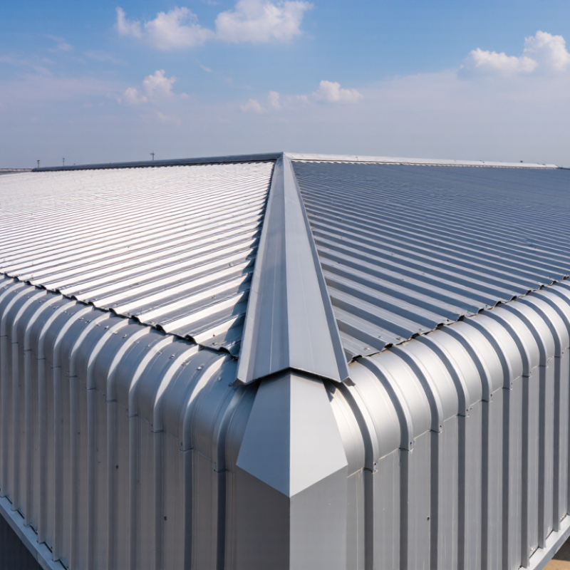
| Base Material | Cold-formed steel sheet with an aluminum-zinc coating | Galvalume coating is primarily aluminum and zinc, commonly with a small silicon addition. The aluminum-rich surface provides barrier protection, while zinc helps provide sacrificial protection at cut edges. | Roofing, wall cladding, agricultural buildings, workshops, and light industrial structures | Steel grade, yield strength, coating standard, and whether the sheet is intended for structural or non-structural use |
| Coating Designation | AZ50 or AZ55 | Under ASTM A792/A792M, AZ50 indicates a minimum total coating mass of approximately 150 g/m² on both sides, while AZ55 indicates approximately 165 g/m² on both sides. | AZ50 for many standard applications; AZ55 where a higher coating mass is preferred | Confirm that the designation refers to total coating mass on both sides, not the coating mass on one side only |
| Coating Thickness | Approximately 20–30 micrometres per side for common commercial coating levels | Actual thickness varies according to coating mass, density, process control, and measurement location. Coating mass is normally a more reliable specification than visual appearance. | Use the higher coating level for more demanding exposure, subject to the project specification | Mill test certificate, coating-mass test method, minimum values, and tolerance requirements |
| Steel Thickness | 0.40–0.50 mm: light-duty; 0.60–0.80 mm: higher rigidity | Increasing base-metal thickness generally improves stiffness, fastener pull-out resistance, dent resistance, and allowable span, but it also increases weight and cost. | Choose thickness from structural calculations rather than appearance alone | Nominal thickness versus base-metal thickness, thickness tolerance, design load, support spacing, and local building code |
| Profile Depth | Approximately 18–35 mm for common corrugated profiles | A deeper corrugation usually increases section stiffness and may permit greater support spacing, provided the sheet thickness and profile geometry are suitable. | Shallower profiles for short spans; deeper profiles for larger spans or higher imposed loads | Profile depth, pitch, crest width, valley width, effective cover width, and published load tables |
| Profile Pitch | Approximately 60–200 mm, depending on the profile design | Pitch affects the number of ribs per sheet, visual appearance, drainage behavior, side-lap arrangement, and effective cover width. | Select a pitch that matches the roof layout, appearance requirements, and compatible accessories | Net cover width after side laps, minimum roof slope, side-lap location, and availability of matching flashings |
| Roof Slope | Often specified at approximately 5° or greater, subject to profile and joint design | The minimum slope depends on profile geometry, sheet length, end laps, weather sealing, rainfall, snow, and wind conditions. A steeper slope generally improves drainage. | Use the profile manufacturer's tested minimum slope and the applicable building code | Minimum slope, end-lap requirements, sealant specification, and local climate exposure |
| Surface Finish | Regular spangle, minimized spangle, or smooth/skin-passed finish | Finish affects visual uniformity and may influence the appearance of paint or protective treatments. It does not replace the need to specify the correct coating mass. | Choose according to appearance, painting requirements, and project specifications | Surface uniformity, oil or passivation treatment, paint compatibility, and allowable cosmetic variation |
| Cut Edges and Fastener Areas | Factory-cut edges with compatible corrosion-resistant fasteners | Galvalume performs well in many atmospheric environments, but exposed cut edges, scratches, trapped moisture, and incompatible metals can accelerate corrosion. | Use correct fasteners, washers, laps, sealants, and edge-protection procedures | Fastener material, washer type, galvanic compatibility, edge treatment, and storage conditions |
| Exposure Conditions | Rural, urban, industrial, coastal, or high-humidity environments | Salt spray, persistent condensation, industrial pollutants, animal waste, and contact with wet concrete or treated timber can reduce service life. | Use a suitable coating, detailing system, and maintenance plan for the actual environment | Site exposure classification, drainage, ventilation, condensation risk, and chemical contaminants |
| Structural Verification | Manufacturer load tables or engineer-designed calculations | Capacity depends on thickness, yield strength, profile geometry, support spacing, fastener layout, wind uplift, snow load, and deflection limits. | Use engineering calculations for occupied, high-wind, snow-load, or long-span structures | Design loads, span tables, allowable deflection, screw pattern, and compliance with local standards |
| Quality Documentation | Inspection certificate and dimensional inspection report | A complete record should identify steel grade, base-metal thickness, coating designation, mechanical properties, dimensions, and test results. | Essential for commercial, industrial, and code-regulated projects | Traceability, batch identification, dimensional tolerances, coating test results, and conformity statement |



 Close
Close