Our company only collects the necessary data and respects your privacy, in accordance with the General Law for the Protection of Personal Data 13.709/2018. By continuing, you confirm that you have read and accepted the Privacy Notice. Privacy Policy.

Medal Pt Br Medal Es

Medal Group

How to Choose an Omni Directional Wheel?

Choosing an Omni Directional Wheel is not simply a matter of selecting the largest load rating. The wheel must match the robot’s mass, floor condition, speed, steering method, and operating environment. A warehouse floor may look smooth, yet small cracks can interrupt roller contact. Dust can also reduce traction and increase vibration. These details matter.

Bengt Ilon, the Swedish engineer associated with the Mecanum wheel, described his invention as “a wheel for a vehicle, which wheel is provided with a plurality of rollers.” That simple idea changed mobile robotics. It also reveals an important design truth: the rollers determine how movement becomes possible. Their angle, material, spacing, and bearing quality affect sideways travel, turning accuracy, noise, and service life.

A practical evaluation should begin with real operating conditions. Measure the maximum static and moving load, then consider uneven weight distribution. Check whether the wheel carries continuous contact during diagonal motion. Compare polyurethane and rubber rollers carefully. Softer materials may grip better, but they can wear faster. Hard rollers may last longer, but they can transmit more vibration.

Do not trust specifications alone.

Testing a prototype on the actual floor is wiser than relying on a catalog chart. Record current consumption, drift, noise, and stopping distance. I have found that many selection errors come from ignoring floor debris and imperfect assembly. That lesson is easy to overlook. A reliable Omni Directional Wheel should provide smooth movement, predictable control, and manageable maintenance, not merely impressive movement in a demonstration.

How to Choose an Omni Directional Wheel?

What Is an Omni Directional Wheel and How Does It Work?

How to Choose an Omni Directional Wheel?

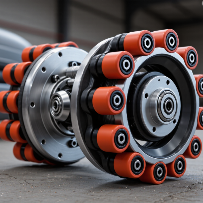
An omni directional wheel uses several small rollers around its rim. The rollers rotate sideways while the main wheel turns forward. This creates movement along two axes with limited steering. A mobile robot can move forward, sideways, or diagonally. It can also rotate within a tight footprint. That matters in narrow aisles, factory cells, and service corridors.

The wheel’s design is not magic. Each roller transfers part of the load, so uneven floors can reduce traction. Check rated load, roller material, wheel diameter, axle strength, and motor torque. Smaller wheels need less space, but they usually struggle with thresholds and floor gaps. The International Federation of Robotics reported about 158,000 professional service robots sold in 2022. Transportation and logistics were among the leading applications in its World Robotics 2023 report. That growth increases demand for precise mobile platforms, but the report does not make every wheel suitable. Real testing remains essential.

Tips: Place the heaviest equipment near the platform center. Measure the floor’s worst gap, not its average surface. Test diagonal movement with the expected payload. Listen for roller vibration. A quiet test may still hide slipping. I have seen designs pass unloaded trials and fail under battery weight. That mistake is easy to repeat. Review acceleration, stopping distance, and roller wear after extended use. A useful wheel is not merely compact; it must remain predictable when conditions become imperfect.

How to Choose an Omni Directional Wheel?

What Is an Omni Directional Wheel and How Does It Work?

This chart compares the idealized motion components available from common wheel arrangements. A fixed wheel mainly supports forward and backward rolling, while an Omni Wheel adds powered sideways motion through its freely rotating rollers. A coordinated multi-wheel omni platform can independently control forward movement, lateral movement, and rotation. In real applications, wheel diameter, load rating, floor condition, roller material, motor torque, and control accuracy should also be considered.

Assess Load Capacity, Wheel Size, and Required Mobility

How to Choose an Omni Directional Wheel?

Load capacity comes before maneuverability. Calculate the vehicle, battery, frame, and payload together. Then divide the total weight by the number of load-bearing wheels. Use a safety margin of at least 25 percent for uneven floors and sudden stops. A small wheel may carry the stated load, but its rollers can suffer impact damage. That detail is easy to miss.

The 2024 MHI Annual Industry Report found that 55% of supply-chain professionals increased technology investment, raising demand for dependable mobile equipment. However, more automation does not excuse weak calculations.

Wheel size changes both mobility and stability. Larger wheels cross floor joints, debris, and cable covers more smoothly. Smaller wheels reduce the chassis height and turning radius. For frequent travel over rough concrete, choose a larger diameter with sealed bearings. For clean, level floors, compact wheels may provide adequate movement.

The International Federation of Robotics reported 541,302 industrial robots installed worldwide in 2023. That growth shows why precise omnidirectional movement matters in busy facilities. Still, wheel geometry, surface material, and roller spacing can affect performance more than diameter alone.

Tips: Measure the narrowest aisle and the largest floor gap. Test the loaded assembly, not an empty prototype. Listen for vibration. If the wheel slips during diagonal travel, reduce speed or reconsider the contact material. A perfect specification on paper can disappoint in real operation.

Compare Wheel Materials for Different Floors and Environments

Choosing an omnidirectional wheel starts with the floor, not the catalogue. I inspect surface texture, joints, moisture, and loose debris before selecting a material. A smooth concrete floor usually suits polyurethane rollers. They provide controlled movement and resist moderate abrasion. They also reduce marking compared with harder plastics. My first choice is not always right.

Nylon wheels handle heavy loads and clean, dry floors well. However, they can sound harsh on tile and may leave marks on delicate surfaces. Rubber offers better grip and quieter travel. It works well on painted floors, wood, and areas where vibration matters. Soft rubber can flatten under heavy loads, especially during long stops. That detail is easy to miss.

Wet or dirty environments require closer attention. Polyurethane often performs better than standard rubber around light moisture and oil exposure, but chemical compatibility must be verified. Steel may tolerate extreme loads and rough concrete, yet it can damage tiles, wood, and coated floors. On uneven surfaces, larger rollers usually cross small gaps more smoothly. Smaller rollers feel responsive but transmit every joint and crack. I once underestimated floor debris, and the wheels collected dust faster than expected. A practical test with the actual load remains more reliable than a material chart. Temperature, cleaning chemicals, and operating speed can change performance, too.

Choose the Right Wheel Layout and Drive Configuration

Choosing an omni directional wheel starts with the layout, not the motor. A three-wheel kiwi drive suits compact platforms and tight turning spaces. A four-wheel mecanum layout offers easier payload distribution and smoother straight travel. However, wheel rollers can lose traction on dust, thresholds, or uneven flooring. The IFR World Robotics 2024 report recorded nearly 200,000 professional service robots sold in 2023, a 30% increase. That growth makes practical wheel selection more important, especially in crowded warehouses and laboratories.

Drive configuration should match the floor, load, and control target. Use independent motors when precise lateral motion matters. Check each wheel’s torque, roller angle, suspension, and contact pressure. A larger wheel improves obstacle clearance, but it increases platform height and motor demand. ISO 3691-4:2023 highlights risk controls for driverless industrial trucks, reminding engineers that motion performance cannot replace safe stopping and sensing. In field testing, I would measure diagonal travel, sideways drift, and turning error with the intended payload. Perfect symmetry on paper may fail after assembly.

Tips: Test the full wheel layout on the real floor. Mark a one-meter square. Record position error after ten sideways movements. Keep at least 20% torque reserve for starts and ramps. Recheck results with worn rollers; this step is easy to miss.

How to Choose an Omni Directional Wheel? - Choose the Right Wheel Layout and Drive Configuration

Compare common omni-directional wheel layouts and select a configuration according to mobility, load requirements, control complexity, floor conditions, and application priorities.

Wheel Layout Typical Wheel Arrangement Drive Configuration Movement Capability Main Advantages Key Limitations Best-Suited Applications Selection Guidance
Two-Wheel Differential Drive with Caster or Slider Two powered wheels mounted on a common axle, with one or more passive supports. Two independently controlled drive motors. The support element is not normally powered. Forward, reverse, and turning around a changing instantaneous center. It does not provide true sideways translation. Simple mechanical design, low controller complexity, good traction, and relatively low cost. Cannot move laterally without rotating first. Passive casters can create scrub, vibration, and alignment issues. Indoor mobile platforms, service robots, line-following systems, and applications where side motion is unnecessary. Choose this layout when simplicity and traction are more important than holonomic movement.
Three-Wheel Kiwi Drive Three omni wheels positioned approximately 120 degrees apart around the chassis. One independently controlled motor per wheel; all three wheel speeds are coordinated by inverse kinematics. Holonomic movement: forward, lateral, diagonal, and rotational motion without changing the chassis heading. Compact, mechanically balanced, and capable of movement in any planar direction. Load distribution is sensitive to chassis geometry and floor irregularities. Wheel contact can be less forgiving on uneven surfaces. Small indoor robots, educational platforms, competition robots, and compact maneuvering systems. Use it when a compact footprint and full planar mobility are needed with three motor channels.
Four-Wheel Omni X-Drive Four omni wheels placed near the four corners, with wheel axes arranged in a coordinated X-drive pattern. Four independently controlled motors with synchronized velocity control. Holonomic movement in forward, lateral, diagonal, and rotational directions. Good maneuverability, straightforward kinematic modeling, and a square or rectangular chassis format. Higher control and calibration requirements than differential drive. Uneven floors can reduce consistent contact between all wheels. Indoor transport robots, automated guided platforms, warehouse equipment, and mobile research systems. Choose this layout when four-wheel stability and all-direction movement are both required on relatively smooth floors.
Four-Wheel Mecanum Drive Four mecanum wheels arranged at the corners. Roller orientation is commonly configured as an X or O pattern when viewed from above. Four independently controlled motors. The controller must account for wheel position and roller orientation. Holonomic movement, including sideways translation, diagonal travel, rotation, and combined motions. Provides omnidirectional motion with a conventional four-corner chassis and no steering mechanism. Roller contact introduces vibration and efficiency losses. Traction and motion accuracy depend strongly on wheel orientation, floor quality, and load distribution. Indoor material-handling platforms, pallet-moving systems, robotics laboratories, and maneuverable inspection vehicles. Verify the X/O wheel orientation before wiring and programming. Use on smooth, firm floors for the most predictable results.
Four-Wheel H-Drive Two parallel powered wheel pairs provide the main drive; an additional lateral wheel or wheel set is mounted across the center of the chassis. Usually uses separate control for the primary drive wheels and the lateral drive wheel. The exact motor count depends on whether wheel pairs are mechanically linked or independently driven. Forward and reverse through the primary wheels, with lateral translation supplied by the center wheel or wheel set. Rotation is normally achieved through differential speed between the main wheels. Can offer lateral motion while retaining a relatively simple rectangular chassis and strong forward traction. The center wheel can experience uneven loading or contact loss. Lateral and longitudinal motion may not be equally smooth under changing payloads. Indoor carts, narrow-aisle platforms, docking systems, and applications requiring occasional side-shifting. Consider it when sideways alignment is useful but full holonomic performance is not required continuously.
Steerable Omni-Wheel Module One or more omni wheels are mounted in steerable modules, allowing the wheel heading to change. Each module generally requires a drive actuator and a steering actuator, with feedback for both axes. Can provide controlled translation and rotation, but motion depends on steering coordination and steering-angle limits. Can combine high traction with flexible wheel orientation and may reduce lateral scrub during certain maneuvers. More mechanical parts, higher cost, more complex calibration, and possible steering backlash or synchronization errors. Heavy mobile equipment, precision positioning platforms, and systems requiring configurable wheel directions. Select this architecture when payload capacity, directional control, or reduced scrub justifies the added mechanical and software complexity.
Passive Omni-Wheel Support System Powered conventional wheels are combined with passive omni wheels or omni casters to support the chassis. Only the primary drive wheels are powered; passive omni wheels rotate freely and do not provide propulsion. Movement is determined by the powered wheels. The passive omni wheels accommodate motion with less resistance than fixed casters. Reduces support friction, simplifies the drive system, and can improve maneuverability compared with fixed casters. Does not create independent lateral propulsion. Passive wheels can still transmit vibration and may require careful height adjustment. Two-wheel robots, carts, small automation platforms, and systems needing low-friction support. Use it when the drive system does not need true holonomic control but passive support resistance must be minimized.
Spherical or Ball-Style Omni Wheel A spherical rolling element or ball transfers load while allowing motion in multiple directions. May be passive, or integrated with a specialized drive mechanism. Motor requirements vary significantly by design. Passive versions support multi-directional movement; powered versions can provide additional directional control if the drive mechanism is sufficiently constrained. Very compact support geometry and low directional resistance in suitable applications. Load capacity, traction, contamination tolerance, and control implementation can be more challenging than with roller-based omni wheels. Light-duty support points, precision mechanisms, conveyors, and compact positioning equipment. Choose it for compact support or specialized mechanisms rather than for high-traction mobile propulsion unless the design is specifically engineered for that purpose.

Practical selection rule: For smooth indoor floors and true omnidirectional movement, three-wheel kiwi, four-wheel omni, or four-wheel mecanum layouts are common choices. For higher traction and simpler control, differential drive is usually preferable. Always verify wheel load rating, contact pressure, floor flatness, motor torque, encoder feedback, and the required number of independent drive channels before finalizing the design.

Check Installation, Maintenance, and Long-Term Performance Needs

How to Choose an Omni Directional Wheel?

Check Installation, Maintenance, and Long-Term Performance Needs

Choosing an omni directional wheel starts with installation, not catalog diameter. Confirm mounting height, bolt pattern, wheel orientation, and floor condition. Even a few millimeters of height mismatch can overload one wheel. Check this with a straightedge and feeler gauge. Calculate payload, frame mass, acceleration, and shock loads together. Do not divide total weight evenly unless the frame stays rigid. It often does not.

Maintenance needs should be clear before purchase. Select sealed bearings only when they suit dust, moisture, and temperature conditions. Inspect roller wear, axle looseness, flat spots, and fastener torque on a documented schedule. The U.S. Department of Energy’s Operations & Maintenance Best Practices Guide estimates that preventive maintenance can reduce costs by 12–18% compared with reactive maintenance. That figure is not guaranteed. It remains a useful budget warning. Keep spare rollers and record inspection findings.

Long-term performance requires realistic testing. Run a loaded trial over floor joints, ramps, and repeated turns. Measure starting force, noise, tracking, and wheel temperature after a defined duty cycle. ISO 20816 can structure vibration measurements, although it is not an omni-wheel qualification standard. Compare trials with supplier load and life-test reports, not marketing claims. Smooth floors can hide poor choices. Small debris exposes them quickly. Recheck the system after 100 operating hours. Some assumptions will be wrong.