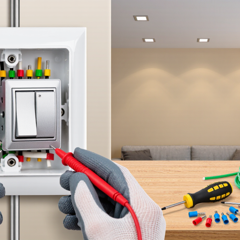
| 1 | Confirm the circuit type | Verify that the light is controlled from two switch locations. A standard three-way circuit has two switches and no ordinary on/off switch with an “ON” or “OFF” position. | Each three-way switch normally has one common terminal, two traveler terminals, and one ground terminal. | Do not begin if the wiring configuration is unclear, damaged, overheated, or lacks a grounding conductor where one is required. |
| 2 | Gather suitable tools | Prepare a listed three-way dimmer, insulated screwdrivers, a non-contact voltage tester, a two-pole voltage tester or multimeter, wire connectors, electrical tape, and a flashlight. | Use a dimmer rated for the lighting load and compatible with the lamp type. Check the installation instructions for minimum and maximum load ratings. | Turn off power before removing the wall plate or touching any conductor. |
| 3 | Turn off the power | At the service panel, switch off the circuit breaker controlling the light. If the correct breaker is unknown, turn off the main disconnect only when it is safe and appropriate to do so. | Do not rely on the wall switch position as proof that the circuit is de-energized. | Keep the breaker off and prevent anyone from restoring power while work is in progress. |
| 4 | Test before contact | Test the existing switch, wires, and the metal electrical box if present. Test the voltage tester on a known energized source before and after checking the circuit. | Check between hot and neutral, hot and ground, and neutral and ground where those conductors are accessible. | A non-contact tester is a screening tool; use an adequately rated contact tester or multimeter to confirm zero voltage. |
| 5 | Document the existing connections | Remove the wall plate and photograph the wiring before disconnecting anything. Label each wire by the terminal it was connected to. | Identify the wire on the differently colored common screw separately from the two traveler wires. Do not depend only on insulation color. | Do not remove wires until the circuit has been tested and the connections have been documented. |
| 6 | Identify the common wire | Find the conductor connected to the common terminal of the existing three-way switch. The common terminal is usually a different color from the two traveler terminals. | The common wire may carry incoming line power or switched power to the light, depending on which switch box is being modified. | Wire colors and cable arrangements can vary. Terminal location and circuit testing are more reliable than color alone. |
| 7 | Identify the travelers | Locate the two wires connected to the matching traveler terminals. These wires run between the two three-way switch locations. | Travelers are interchangeable on a standard three-way switch, but they must not be connected to the dimmer’s common terminal. | Keep the traveler pair together and preserve the original cable routing. |
| 8 | Check the neutral and ground | Look for a neutral conductor in the box if the dimmer requires one. Identify the grounding conductor or grounded metal box where applicable. | Neutral conductors are commonly white, but a white wire may be repurposed in some older installations and must be verified. Grounding conductors are commonly bare or green. | Never use a grounding conductor as a neutral, and never disconnect or remove a required grounding connection. |
| 9 | Check dimmer compatibility | Confirm that the dimmer is specifically designed for three-way operation and that the existing companion switch is compatible with the dimmer’s wiring method. | Some dimmers require a neutral; others do not. Some require a specific companion control instead of a standard three-way switch. | Follow the wiring diagram supplied with the exact dimmer. Do not assume all three-way dimmers use the same terminals. |
| 10 | Disconnect the existing switch | With power verified off, loosen the terminal screws and remove the wires. Keep the common wire clearly labeled. | Do not place more than the permitted number of conductors under a terminal. Use approved connectors when joining wires. | Inspect for loose strands, scorched insulation, corrosion, or wires that are too short to make a secure connection. |
| 11 | Connect the three-way dimmer | Connect the labeled common wire, the two traveler wires, the grounding conductor, and the neutral if required by the dimmer’s instructions. | Terminal names may include common, line, load, traveler, neutral, and ground. “Line” and “load” must be connected as specified by the installation diagram. | Make tight, approved connections with no exposed copper extending beyond the terminal or connector. |
| 12 | Secure the dimmer in the box | Fold the wires carefully into the electrical box and attach the dimmer without pinching or sharply bending the conductors. | The device should sit straight and the mounting screws should be secure without damaging the box or device yoke. | Do not force an overcrowded device into the box. Box-fill requirements may limit the number and size of conductors allowed. |
| 13 | Install the wall plate | Fit the wall plate after confirming that no bare energized part is exposed and that the device is properly aligned. | Use a plate suitable for the device shape and tighten screws evenly without cracking the plate. | Keep the wall plate installed during normal use to reduce accidental contact with wiring. |
| 14 | Restore power and test | Restore power at the breaker. Test the dimmer at low, medium, and high settings from both switch locations. | Confirm that the light turns on and off from either location and that brightness changes smoothly without abnormal noise or flicker. | Turn power off immediately if there is sparking, heat, buzzing, a burning smell, tripped protection, or unexpected operation. |
| 15 | Perform a final inspection | Check that the device is firmly mounted, the plate is secure, and the dimmer does not become unusually warm during normal operation. | Recheck the lamp’s load type and total wattage if flicker, limited dimming range, or shutdown occurs. | Stop work and consult a qualified electrician when the circuit has aluminum wiring, multiple circuits in one box, missing grounding, heat damage, or uncertain connections. |



 Close
Close