What Is a Hydraulic Pressure Pump and How Does It Work?
A Hydraulic Pressure Pump sits at the heart of many machines, from excavators to factory presses. Its job is to move hydraulic fluid through a circuit. Resistance from a cylinder, motor, or restricted passage creates pressure. This distinction matters. A pump supplies flow; the system’s load determines pressure. Confusing the two can lead to poor component selection and costly troubleshooting.
Industry evidence helps explain why these systems deserve careful attention. The National Fluid Power Association’s annual industry outlook and shipment data track demand across fluid-power markets. Grand View Research’s Hydraulic Pump Market Size, Share & Trends Analysis Report provides a broader view of applications and market direction. These sources offer useful context, but market growth alone does not prove that one pump design suits every job. ISO 4409:2019 provides standardized methods for testing hydraulic pumps, including performance measurements under defined conditions. That matters. Real performance also depends on fluid cleanliness, operating temperature, speed, and installation. Picture a pump turning beside a warm reservoir, pushing oil through a hose toward a loaded cylinder. Small changes in oil viscosity or a clogged filter can affect the whole circuit. This guide explains what a Hydraulic Pressure Pump is, how its main components work, and how flow, pressure, and load interact. It also examines common pump types and practical selection factors. One detail is easy to overlook: a pump may be correctly sized on paper yet perform poorly in an unsuitable system. That deserves a second look.
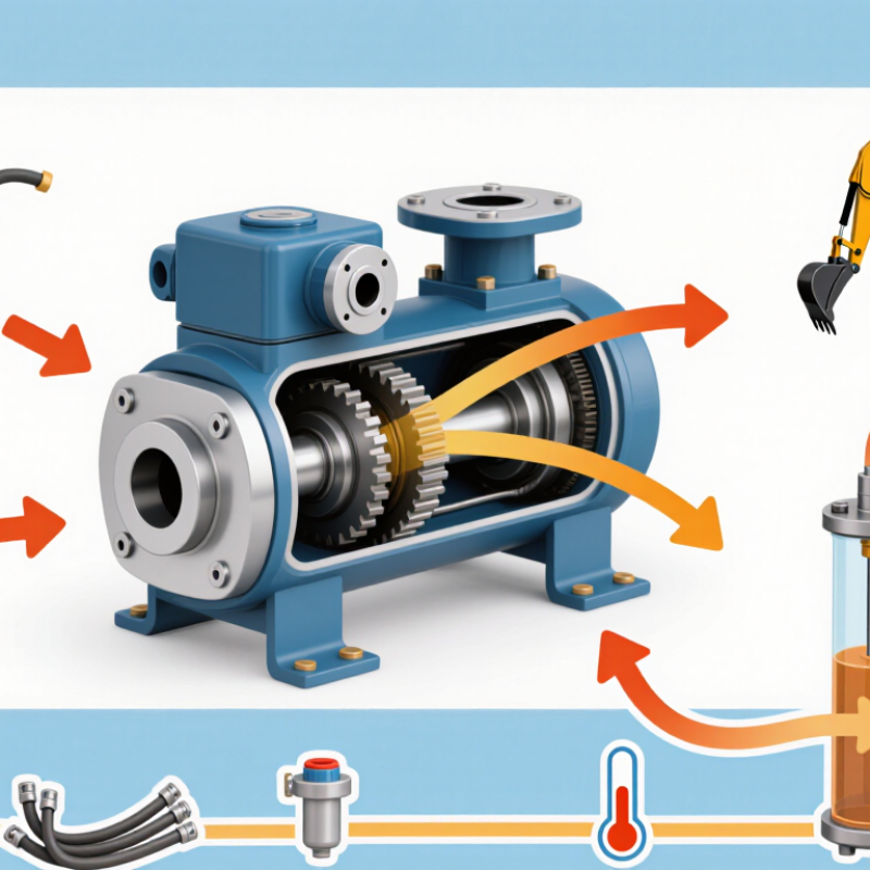
Hydraulic Pressure Pumps: Core Parts and Typical 70–350 bar Systems
A hydraulic pressure pump converts mechanical shaft power into fluid flow; resistance in the circuit creates pressure. In typical 70–350 bar systems, a motor drives a gear, vane, or piston pump. The reservoir, inlet strainer, filters, pressure-relief valve, hoses, and actuator complete the circuit. A gauge near the pump helps operators compare working pressure with the system’s rated limit. Small parts matter.
ISO 4413:2010 sets general rules for hydraulic system design, including pressure control and protection against hazards. For fluid cleanliness, ISO 4406:2021 uses particle counts at ≥4, ≥6, and ≥14 μm(c) to define contamination codes. Those numbers matter: particles can accelerate wear in close-fitting pump components. A clogged filter can also restrict flow and raise fluid temperature.
At 70 bar, a compact cylinder may move a light fixture smoothly; at 350 bar, fittings and hoses need ratings suited to that pressure. Never treat the range as a universal pump rating. Check the nameplate, relief setting, fluid viscosity, and duty cycle together. One easy mistake is focusing on pressure alone. A pressure reading tells only part of the story; flow and temperature deserve attention too.
Pascal’s Law: How Pressure Creates Force (F = P × A)
A hydraulic pressure pump moves oil through a sealed circuit. Pascal’s Law explains what happens next: pressure applied to a confined fluid is transmitted throughout it. The pump supplies flow; resistance from a cylinder or load allows pressure to build. Pressure is not force by itself.
The relationship is F = P × A, where F is force, P is pressure, and A is the piston’s effective area. For example, pressure of 10 megapascals acting on a 0.01-square-meter piston produces a theoretical force of 100,000 newtons. That is a substantial push. A larger piston creates more force at the same pressure, though it usually moves more slowly for the same fluid flow. A small piston can travel farther while driving a larger one.
Real systems are less tidy. Seals flex, oil warms, and friction eats into useful force. Gauge readings can also differ from pressure at the actuator, especially across long hoses or restrictive valves. So the equation is a clear starting point, not a complete performance prediction. Engineers compare measured pressure, piston area, and actual movement; sometimes the mismatch is the useful clue.
Hydraulic Pressure and Ideal Force
Pascal’s law explains how pressure applied to a confined fluid is transmitted throughout the fluid. For a fixed piston area, force increases with pressure: F = P × A. This chart assumes a piston area of 10 cm² (1,000 mm²) and shows ideal force; real systems may produce less force due to friction and other losses.
Pump Displacement and Speed: Estimating Flow (Q ≈ Vd × rpm)
A hydraulic pump’s displacement, Vd, is the volume moved per shaft revolution. Estimate theoretical flow with Q ≈ Vd × rpm. Take a 28 cm³/rev pump turning at 1,500 rpm. Its theoretical flow is 42 L/min: 28 × 1,500 ÷ 1,000. That is an estimate, not guaranteed delivery. Leakage, oil viscosity, wear, and pressure reduce actual flow. At an assumed 90% volumetric efficiency, output is about 37.8 L/min. Treat that efficiency as an estimate; measure the actual unit.
The U.S. Department of Energy’s 2006 Improving Pumping System Performance: A Sourcebook for Industry reports that pumping systems use nearly 20% of global electricity. That figure covers many pump types, not hydraulic circuits alone, but it shows why flow estimates matter. For positive-displacement pumps, ISO 4409:2019 specifies methods for testing and reporting steady-state performance. Compare calculated flow with measured flow at operating pressure. A cold bench test may mislead.
Tips: Confirm displacement units, then convert to L/min. Use actual shaft rpm, especially with a gearbox or variable-speed drive. Record pressure, oil temperature, and flow together. A tidy calculation can still hide a worn pump; that caveat is easy to miss.
Relief Valves: Setting Pressure Limits to Protect the Circuit
A hydraulic pressure pump supplies oil flow, while circuit resistance creates pressure. A relief valve limits that pressure.
It usually stays closed during normal operation, then opens when pressure reaches its set point. Excess oil flows back to the reservoir or another low-pressure path, reducing the load on hoses, seals, and actuators. That is the safeguard.
The setting needs careful thought. It should exceed the pressure required for the task, yet remain below the rating of the circuit’s weakest component.
A gauge helps, but a brief pressure spike may be missed, and a worn gauge can mislead. Small details matter. Oil temperature, contamination, and valve condition can affect performance.
In practice, technicians check the valve against the system’s specifications and make adjustments with suitable test equipment. Turning the adjustment screw too far can raise the limit beyond safe component ratings.
A relief valve also does not correct every problem: a blocked line or undersized pump may still cause poor operation. Check for leaks, unusual heat, or repeated valve chatter, then investigate the cause rather than simply increasing the setting.
Gear, Vane, and Piston Pumps: Comparing Typical Pressure Ratings
A hydraulic pump moves oil; system resistance creates pressure. This distinction matters when comparing ratings. Gear pumps are commonly rated around 1,000–3,000 psi, making them a practical choice for many standard circuits. Their simple construction handles steady work well, but sustained pressure near the upper limit can increase heat and wear. Check the continuous rating, not just a brief peak figure.
Vane pumps often operate around 1,000–2,500 psi. They can deliver relatively smooth flow, which helps reduce vibration in equipment such as machine tools. Piston pumps commonly cover roughly 3,000–6,000 psi, with some designs rated higher. They suit demanding systems, but usually require closer attention to oil cleanliness and maintenance. These ranges are typical, not guarantees: displacement, speed, temperature, and the specific pump design all affect performance. A pressure chart can look reassuring while leaving out duty cycle. That deserves a second look. Match the pump’s continuous rating to the system’s real load, and treat peak pressure as a short-duration limit.



 Close