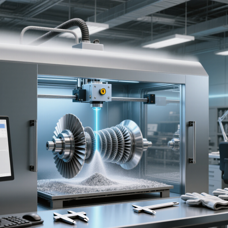
| 1. Digital Design | A three-dimensional CAD model is converted into a mesh and positioned in the build volume. | CAD software, STL or 3MF file, build-orientation settings | The model is divided into horizontal layers before printing. | A machine-readable build file containing tool paths and process parameters |
| 2. Metal Feedstock Preparation | The printer receives metal powder, metal wire, or metal-bound filament, depending on the technology. | Stainless steel, aluminum, titanium, nickel alloys, tool steel, or other qualified metals | Powder-based systems commonly use particles about 15–63 micrometers in diameter; exact specifications vary. | Consistent feedstock suitable for controlled layer deposition |
| 3. Build-Plate Preparation | A metal build plate is installed, leveled, and often heated or surface-treated to improve adhesion. | Build plate, fixtures, calibration tools, inert process environment | The build plate provides mechanical support and helps reduce distortion during manufacturing. | A stable foundation for the first printed layer |
| 4. Layer Deposition | A thin layer of feedstock is spread or deposited over the build area. | Recoater blade, powder hopper, wire feeder, or filament drive system | Common powder-bed layer thickness is approximately 20–60 micrometers; larger values may be used for faster production. | A uniform layer of metal feedstock ready for selective bonding |
| 5. Selective Melting or Bonding | A heat source follows the programmed tool path and melts, sinters, or bonds selected regions of the layer. | Laser, electron beam, arc, or heated nozzle, depending on the process | Laser and electron-beam systems can locally melt metal at temperatures above the alloy melting point. | A solidified cross-section that forms part of the final component |
| 6. Recoating and Repetition | The platform moves by one layer height, a new layer is added, and the heat source repeats the programmed pattern. | Motion system, sensors, control software, protective gas or vacuum chamber | The cycle continues for hundreds or thousands of layers, depending on part height. | A three-dimensional near-net-shape metal part |
| 7. Atmosphere Control | The process environment is controlled to limit oxidation and contamination while the metal is heated. | Argon or nitrogen for many powder-bed and directed-energy systems; vacuum for some electron-beam processes | Oxygen levels are commonly controlled to low concentrations, with the required limit determined by the material and process. | Improved melt-pool stability and reduced oxidation risk |
| 8. Cooling | The printed part cools in a controlled manner after the final layer is completed. | Build chamber, inert gas circulation, thermal monitoring | Cooling time may range from several minutes to many hours, depending on part size, material, and machine settings. | A cooled part that can be safely removed for post-processing |
| 9. Part Removal | The component is separated from the build plate, and temporary support structures are removed. | Band saw, wire electrical-discharge machining, milling, or manual tools | Support structures are often required for overhangs, heat conduction, and part stability. | A free-standing printed component with residual support material removed |
| 10. Heat Treatment | Thermal processing can relieve residual stress and adjust the material microstructure. | Stress-relief, annealing, hot isostatic pressing, or solution and aging treatments | The required temperature and duration depend on the alloy and target properties. | Improved dimensional stability, density, ductility, or fatigue performance |
| 11. Surface Finishing | Machining, blasting, tumbling, polishing, or chemical treatment improves dimensional accuracy and surface quality. | CNC machining, abrasive media, polishing tools, finishing chemicals | As-built surfaces are typically rougher than machined surfaces; the final finish depends on orientation and process settings. | A smoother surface and tighter dimensional tolerances |
| 12. Inspection and Qualification | The finished part is checked for dimensions, internal defects, density, surface condition, and mechanical performance. | Calipers, coordinate-measuring machines, computed tomography, microscopy, tensile testing | Inspection may include dimensional checks, density verification, and testing against the required design standard. | A documented assessment of whether the part meets its intended requirements |



 Close
Close