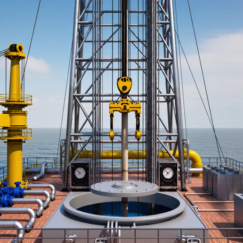
| Substructure | Primary structural support | Supports the rig floor, mast or derrick, drawworks, and well-control equipment above the wellhead. | Transfers vertical equipment loads and drilling loads into the foundation, conductor system, or supporting hull. | Usually consists of welded steel frames, beams, legs, and bracing. Its height provides clearance for the blowout preventer and wellhead equipment. | Must resist compression, lateral forces, vibration, fatigue, wind, wave, and equipment loads. |
| Mast or Derrick | Hoisting structure | Provides vertical support for the crown block, traveling equipment, drill string, and tubular handling operations. | The structure carries suspended loads while allowing the traveling block to move vertically through its working range. | Typically a tall, open-lattice steel structure. A mast is commonly designed to be erected or lowered, while a derrick is generally assembled in sections. | Designed for hook load, wind load, dynamic movement, fatigue, and stability during raising, lowering, and drilling. |
| Rig Floor | Working platform | Provides the main working area for drilling personnel and supports rotary, pipe-handling, and well-control equipment. | Distributes equipment and personnel loads into the substructure while maintaining access around the well center. | Includes deck beams, grating or plate flooring, handrails, access points, and openings for tubulars and well-control equipment. | Requires slip resistance, drainage, fire protection, safe access, and resistance to concentrated equipment loads. |
| Crown Block | Hoisting system | Forms the stationary upper pulley assembly of the main hoisting system. | Wire rope is reeved between the crown block and traveling block, multiplying lifting capacity through multiple lines. | Mounted at the top of the mast or derrick and fitted with sheaves sized for the drilling line and rated load. | Must withstand repeated lifting cycles, line tension, sheave rotation, bearing loads, and fatigue. |
| Traveling Block | Hoisting system | Raises and lowers the drill string, casing, completion equipment, and other tubulars. | Moves vertically as the drawworks pays out or reels in the drilling line reeved through the crown block. | Contains multiple sheaves and is connected to the hook. The block weight and rated capacity vary with the rig's hoisting design. | Subject to hook load, acceleration, braking forces, line tension, impact, and fatigue from repeated trips. |
| Drawworks | Hoisting and power transmission | Controls the drilling line to lift, lower, suspend, and position the traveling block. | Powered drums wind or unwind the drilling line. Braking and control systems regulate block speed and hold suspended loads. | Includes a drum, brake system, transmission or drive, clutches or equivalent controls, and drilling-line spooling equipment. | Requires reliable braking, heat dissipation, emergency stopping, line management, and protection against overload. |
| Hook and Swivel | Load connection and fluid transfer | Suspends the drill string and permits rotation and drilling-fluid circulation through the drill string. | The hook connects the traveling block to the swivel. The swivel supports the rotating string while maintaining a sealed fluid passage. | Located below the traveling block and above the kelly or top-drive connection, depending on the rig configuration. | Must handle tensile load, torque transmission interfaces, pressure containment, wear, and continuous rotation. |
| Top Drive | Drill-string rotation | Rotates the drill string and provides a path for drilling fluid while allowing drilling in stand-length sections. | An electric or hydraulic motor turns the drill string from a carriage suspended in the mast or derrick. | Usually travels vertically along guide rails and integrates a pipe-handler, saver-sub connection, and fluid swivel. | Designed for torque, axial load, pressure, vibration, cooling, service access, and reliable control. |
| Rotary Table | Drill-string rotation | Rotates the drill string and supports slips when a conventional rotary drilling arrangement is used. | A powered table turns a drive bushing that engages the kelly or another rotary component. Slips hold tubulars in the well center. | Installed in the rig floor around the rotary opening. It may be the primary rotation device or used alongside a top drive. | Must resist torque, axial load, shock, wear, and debris while maintaining accurate well-center alignment. |
| Mud Pumps | Drilling-fluid circulation | Circulate drilling fluid down the drill string and back to the surface through the annulus. | Reciprocating pistons or plungers draw fluid from the suction system and discharge it at high pressure into the standpipe manifold. | Commonly positive-displacement pumps with replaceable liners, pistons, valves, dampeners, and pressure-monitoring equipment. | Designed for flow rate, discharge pressure, pulsation control, abrasion, seal life, and safe pressure relief. |
| Standpipe and Rotary Hose | High-pressure fluid piping | Conveys drilling fluid from the mud pumps to the swivel or top drive. | The standpipe provides a fixed vertical route; the flexible rotary hose accommodates movement of the traveling equipment. | Constructed from pressure-rated piping, valves, unions, and flexible hose assemblies suitable for drilling-fluid service. | Must withstand internal pressure, pulsation, vibration, movement, erosion, temperature, and connection loads. |
| Blowout Preventer Stack | Well control | Seals the wellbore and controls formation pressure during drilling and well operations. | | Installed below the rig floor on land or on the wellhead system offshore. The stack includes preventers, spools, valves, and control lines. | Requires pressure integrity, tested closure performance, hydraulic control reliability, erosion resistance, and safe venting or choke routing. |
| Wellhead and Casing Head | Well support and pressure control | Supports casing strings, seals the annulus, and provides the connection point for well-control equipment. | Hangers suspend casing, seals isolate annular spaces, and outlets allow monitoring or controlled access to the wellbore. | Located at the surface or on the seabed, depending on the drilling unit and well arrangement. | Must withstand well pressure, casing loads, thermal effects, corrosion, sealing forces, and installation tolerances. |
| Drill String | Downhole drilling assembly | Transmits rotation and weight to the bit while carrying drilling fluid to the bottom of the well. | Drill pipe connects the surface equipment to heavy-weight drill pipe, drill collars, bottom-hole assemblies, and the bit. | Made from threaded tubular sections with tool joints and specialized downhole components selected for the well profile. | Subject to tension, compression, torsion, bending, internal pressure, buckling, vibration, and fatigue. |
| Casing and Cementing System | Wellbore integrity | Stabilizes the wellbore, isolates formations, protects groundwater zones, and provides pressure barriers. | Steel casing is run into the hole and cement is placed in the annulus to bond the casing to the formation. | Casing strings are installed in stages with decreasing diameters as depth increases. Cement placement is verified through testing and evaluation. | Designed for burst, collapse, axial load, temperature, corrosion, cement bonding, and formation-pressure differences. |
| Shale Shakers | Solids control | Remove large drilled cuttings from the returning drilling fluid. | Vibrating screens separate solids by particle size while allowing reusable fluid to pass into the active mud system. | Installed near the flowline and mud tanks; screen selection depends on fluid properties, flow rate, and expected cuttings size. | Requires vibration isolation, screen integrity, adequate processing capacity, wear resistance, and safe handling of cuttings. |
| Mud Tanks and Mixing Equipment | Drilling-fluid processing | Store, condition, mix, and circulate drilling fluid before it is pumped back into the well. | Agitators keep solids suspended, while mixing hoppers and chemical-addition systems adjust fluid density and properties. | Includes active tanks, reserve tanks, transfer pumps, agitators, level instruments, and fluid-treatment equipment. | Must provide adequate volume, containment, corrosion resistance, overflow protection, and accurate fluid monitoring. |
| Power Generation and Distribution | Energy supply | Provides mechanical or electrical power for hoisting, rotation, pumping, lighting, controls, and auxiliary systems. | Prime movers drive generators or mechanical transmissions, while switchgear and control systems distribute power to major loads. | May include engines, generators, fuel systems, electrical panels, transformers, cables, and emergency power equipment. | Designed for load changes, redundancy, fuel safety, grounding, short-circuit protection, ventilation, and emissions control. |
| Marine Hull, Legs, or Jacking System | Offshore support structure | Supports the drilling package and maintains the unit's position and elevation offshore. | Jack-up units use legs and elevating systems; semisubmersibles use pontoons and columns; drillships use a ship-shaped hull and station-keeping system. | Configuration depends on water depth, environmental conditions, mobility requirements, and whether the unit floats or stands on the seabed. | Must resist wave, wind, current, buoyancy, stability, fatigue, mooring or thruster forces, and storm conditions. |



 Close
Close