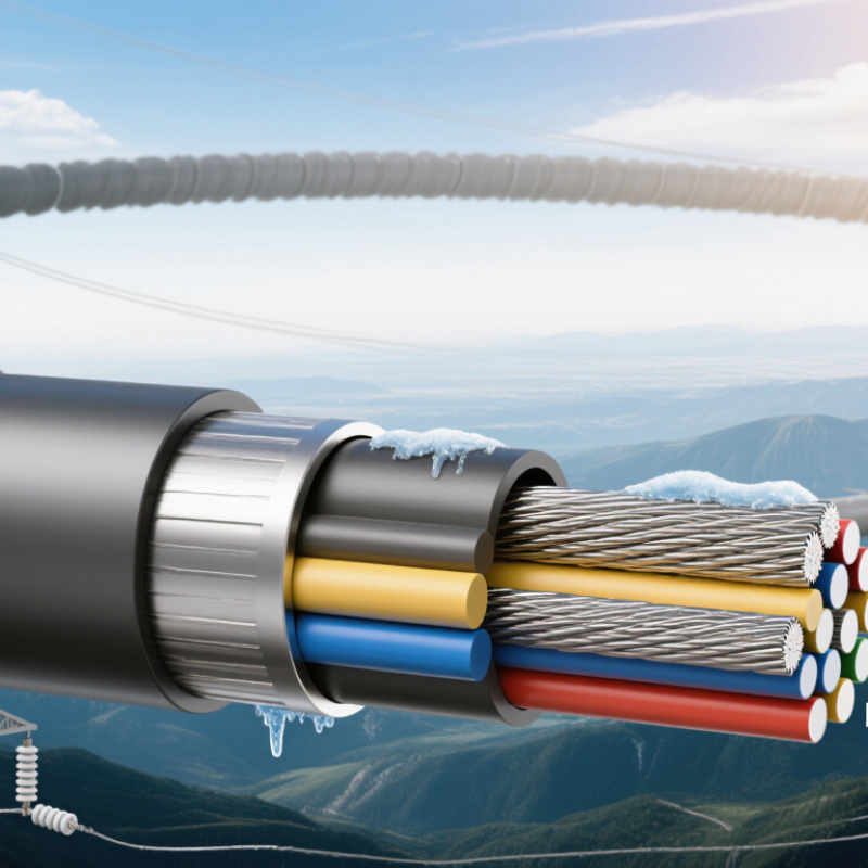
| Basic Definition | OPGW meaning | Optical Ground Wire; a composite overhead earth wire containing optical fibers. | It combines lightning shielding, fault-current conduction, and high-speed communication in one transmission-line component. |
| Installation position | Normally installed at the top of transmission towers as a shield wire. | The tower arrangement and shield angle must be checked to maintain adequate protection against direct lightning strikes. |
| Primary functions | Lightning shielding, short-circuit current path, and optical telecommunications. | The selected design must satisfy both electrical grounding requirements and mechanical overhead-line requirements. |
| Common reference standards | IEC 60794-4, IEEE 1138, and applicable national overhead-line standards. | The project specification should identify the governing standard, test methods, environmental conditions, and acceptance criteria. |
| Main Components | Optical fibers | Usually single-mode fibers, commonly compliant with ITU-T G.652.D or G.655 requirements. | Choose fiber type according to transmission distance, wavelength, dispersion requirements, and network architecture. |
| Fiber count | Common configurations include 12, 24, 36, 48, 72, and higher fiber counts. | Provide enough fibers for current services, protection, maintenance, and planned network expansion. |
| Optical unit | A stainless-steel tube, aluminum tube, or stranded optical unit surrounding the fibers. | The unit protects fibers from moisture, crushing, vibration, thermal effects, and installation strain. |
| Central tube or buffer structure | Fibers are loosely contained to provide excess length and reduce tensile stress transfer. | Loose-tube construction helps maintain optical performance during temperature changes and mechanical loading. |
| Metallic strength members | Aluminum-clad steel, aluminum alloy, galvanized steel, or combinations of these wires. | The metallic layers provide tensile strength, electrical conductivity, thermal capacity, and resistance to environmental loads. |
| Water-blocking materials | Water-blocking gel, dry water-blocking tape, or water-swellable yarns. | These materials limit longitudinal water migration and help protect the fibers over the service life. |
| Protective outer surface | The outer stranded metallic layer forms the weather-resistant and electrically conductive surface. | Surface construction affects corrosion resistance, allowable current, vibration behavior, and compatibility with fittings. |
| Key Electrical Data | Rated tensile strength | Project-specific; often selected from several kilonewtons to tens of kilonewtons. | It must withstand everyday tension, wind, ice, installation loads, and the required safety factors. |
| Short-circuit current rating | Specified in kA for a defined fault duration, commonly 0.5 s or 1.0 s depending on the system study. | Select the cross-sectional area and material combination based on fault current, duration, initial temperature, and permissible final temperature. |
| DC resistance | Specified in ohms per kilometer at a reference temperature, usually 20 °C. | Lower resistance improves fault-current performance and reduces voltage rise between tower grounding points. |
| Lightning current capability | Determined by metallic area, material, strand construction, and thermal limits. | Verify the design against the expected lightning environment and tower shielding requirements. |
| Induced-current and magnetic effects | Depend on line geometry, phase currents, grounding arrangement, and OPGW impedance. | System studies may be required where parallel circuits or high continuous currents create significant induction. |
| Optical attenuation | Common single-mode fiber limits are approximately 0.35 dB/km at 1310 nm and 0.22 dB/km at 1550 nm, subject to the specified fiber grade. | Use the guaranteed project value, including splice, connector, aging, and repair margins, for link-budget calculations. |
| Key Mechanical Data | Overall diameter | Common transmission-line designs are approximately 8–20 mm in diameter, although larger designs are possible. | Diameter affects mass, wind area, ice loading, sag, fittings, and tower-head clearance. |
| Unit mass | Often approximately 250–1,000 kg/km, depending on diameter, metallic area, and fiber configuration. | Check tower loading, foundation reactions, stringing equipment, and installation limitations. |
| Elastic modulus | A calculated or tested composite value based on the strand materials and construction. | Required for sag-tension calculations and should be consistent with the selected installation method. |
| Coefficient of thermal expansion | A composite property influenced by the proportions and arrangement of steel and aluminum-based wires. | Use the manufacturer’s verified value to predict sag at minimum, everyday, and maximum operating temperatures. |
| Bending performance | Must meet specified minimum bending radius and fiber strain limits during handling and installation. | Improper sheave diameter, pulling tension, or sharp bends can cause permanent optical attenuation. |
| Vibration resistance | Designed for aeolian vibration, galloping, and subspan motion according to the line environment. | Assess the need for vibration dampers and ensure the selected fittings match the OPGW construction. |
| How to Choose OPGW | 1. Determine fiber capacity | Define active fibers, protection fibers, spare fibers, and future expansion requirements. | Avoid selecting fiber count only from present demand; replacement or additional installation may be difficult after energization. |
| 2. Check fault-current duty | Use the maximum prospective fault current and clearing time from the protection study. | The OPGW must remain mechanically and electrically suitable after the thermal fault event. |
| 3. Perform sag-tension analysis | Consider span length, ruling span, temperature range, wind pressure, ice thickness, and installation tension. | Confirm clearance to conductors, towers, roads, buildings, vegetation, and other infrastructure. |
| 4. Match tower and fittings | Verify suspension clamps, dead-end assemblies, bonding leads, splice closures, and grounding connections. | Fittings must be compatible with the OPGW diameter, strand construction, rated tensile strength, and short-circuit requirements. |
| 5. Evaluate environment | Review wind, ice, temperature, altitude, pollution, salt exposure, corrosion, and lightning conditions. | Material selection and corrosion protection should reflect the actual route environment rather than a generic catalogue value. |
| 6. Confirm optical performance | Check attenuation, chromatic dispersion, polarization characteristics, fiber strain, splice compatibility, and optical return loss. | The complete link budget should include cable length, splices, connectors, repair reserves, and the required operating margin. |
| Inspection and Testing | Routine production tests | Dimensional inspection, fiber attenuation measurement, tensile-related checks, and electrical resistance verification. | Confirm that every manufactured drum meets the approved technical specification. |
| Type tests | Mechanical, environmental, thermal, vibration, optical, and short-circuit performance tests as applicable. | Type-test evidence demonstrates that the design is suitable for the specified service conditions. |
| Installation inspection | Check drum condition, pulling tension, bending radius, sag, clamps, grounding, and splice closures. | Installation records help identify mechanical or optical damage before commissioning. |
| Optical acceptance test | Use an optical time-domain reflectometer and light-source/power-meter measurements at the specified wavelengths. | Compare measured results with the approved link budget and investigate abnormal splice loss or reflective events. |



 Close