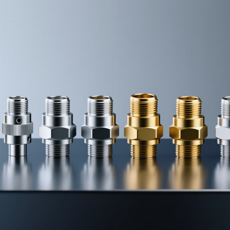
| 1 | Cable plug | Coaxial cable termination; push-on blind-mate interface | Removable cable assemblies connecting to a panel or module | Match cable type, center-conductor attachment, outer-conductor termination, and cable retention method. |
| 2 | Cable jack | Coaxial cable termination; receptacle-side mating interface | Cable ends that mate with compatible blind-mate plugs | Check gender, cable compatibility, contact style, and the specified mating partner. |
| 3 | PCB vertical receptacle | Board-mounted, typically oriented perpendicular to the PCB | Module-to-module or board-to-board RF connections | Confirm PCB footprint, board thickness, mounting method, and allowable mating misalignment. |
| 4 | PCB right-angle receptacle | Board-mounted, with the mating axis parallel to the PCB | Compact assemblies where a horizontal RF connection is needed | Review board-edge clearance, footprint, launch geometry, and mechanical support. |
| 5 | PCB edge-launch receptacle | Mounted at a PCB edge; signal transition connects to the board transmission line | Test fixtures and compact board-level RF interfaces | Check board thickness, edge preparation, launch footprint, and required impedance matching. |
| 6 | Two-hole flange receptacle | Panel or chassis mount using a two-hole flange | Fixed RF ports on equipment panels and module walls | Verify hole spacing, flange outline, panel thickness, and grounding contact. |
| 7 | Four-hole flange receptacle | Panel or chassis mount using a four-hole flange | Applications requiring a bolted mounting pattern | Match the mounting pattern and available panel area; check fastener access and sealing requirements. |
| 8 | Bulkhead receptacle | Passes through a panel or enclosure wall, commonly secured by a nut | RF connections through equipment enclosures | Check panel-hole diameter, thread and nut arrangement, wall thickness, and sealing needs. |
| 9 | Right-angle cable receptacle | Cable termination with a 90-degree body orientation | Cable routing in space-constrained assemblies | Assess bend clearance, cable exit direction, strain relief, and assembly access. |
| 10 | In-line adapter | Two compatible coaxial interfaces joined in a compact in-line body | Joining assemblies or adapting between compatible SBMA terminations | Confirm interface compatibility, gender arrangement, impedance, and added insertion loss. |



 Close