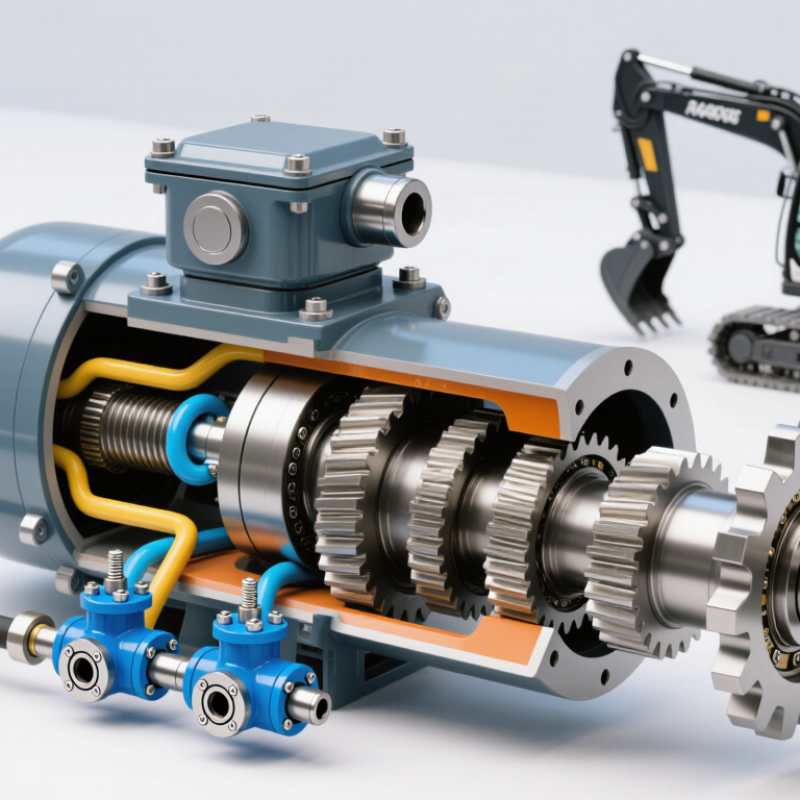
| Basic Definition | Compact hydraulic drive unit | A small travel motor converts pressurized hydraulic fluid into rotary motion to move tracked equipment, compact carriers, mini excavators, and similar machinery. |
| Primary Energy Source | Hydraulic fluid under pressure | The hydraulic pump supplies pressurized oil through control valves and hoses to the motor. The motor then produces mechanical rotation. |
| Common Motor Type | Orbital, gerotor, radial-piston, or axial-piston | Orbital and gerotor designs are common in compact, low-to-medium-speed applications. Piston designs are often selected when higher pressure, efficiency, or durability is required. |
| Typical Displacement | 10–80 cm³/revolution | Displacement is the theoretical volume of hydraulic fluid required for one shaft revolution. A larger displacement generally produces more torque at the same pressure. |
| Typical Operating Pressure | 140–250 bar continuous; up to about 300–350 bar peak | Actual limits depend on the motor design, hydraulic circuit, fluid condition, temperature, and manufacturer’s specifications. Continuous and peak ratings should not be treated as interchangeable. |
| Typical Speed Range | 20–300 rpm | Travel motors generally operate at relatively low shaft speeds while delivering high torque. Speed depends mainly on hydraulic flow and motor displacement. |
| Typical Flow Range | 5–30 L/min | Hydraulic flow controls rotational speed. For an ideal motor, speed in revolutions per minute is approximately calculated as: flow × 1,000 ÷ displacement. |
| Estimated Output Torque | Approximately 30–600 N·m | Torque varies with displacement, pressure, and mechanical efficiency. A simplified estimate is: torque ≈ pressure × displacement ÷ (2π), before efficiency losses are included. |
| Operating Principle | Pressure differential creates rotation | Fluid entering one port acts on internal gears, pistons, or vanes. The pressure difference generates turning force, and the low-pressure fluid exits through the return port. |
| Directional Control | Two hydraulic flow directions | Reversing the inlet and outlet flow reverses shaft rotation. A directional control valve is commonly used to select forward, reverse, and neutral operation. |
| Speed Control Method | Flow-control valve or variable pump | Reducing flow normally reduces motor speed, while increasing flow raises speed until the motor’s rated limit is reached. Excessive restriction can generate heat. |
| Torque Control Method | System pressure and displacement | Torque rises with hydraulic pressure and motor displacement. A relief valve is used to limit system pressure and protect the motor and other components. |
| Typical Efficiency | Overall efficiency commonly about 70–90% | Volumetric, mechanical, and hydraulic losses reduce the theoretical output. Efficiency changes with load, speed, pressure, temperature, and fluid cleanliness. |
| Common Drive Arrangement | Motor with reduction gearbox | A planetary or spur reduction stage may be added to reduce output speed and increase wheel or sprocket torque for tracked travel systems. |
| Main Components | Housing, rotating element, shaft, bearings, seals, ports, and valve parts | The internal components depend on the motor type. Travel assemblies may also include a brake, reduction gear, pressure-relief valves, and a two-speed mechanism. |
| Hydraulic Fluid Requirement | Clean anti-wear hydraulic oil of the specified viscosity | Fluid grade and viscosity must match the operating temperature and motor requirements. Contamination can accelerate wear, damage seals, and reduce efficiency. |
| Heat Generation | Increases with leakage, restriction, and overload | Hydraulic losses are converted into heat. Correct sizing, adequate cooling, clean fluid, and properly adjusted relief valves help control operating temperature. |
| Common Protection Features | Relief valve, anti-cavitation valve, and mechanical brake | Relief valves limit pressure, anti-cavitation valves protect against low-pressure conditions, and brakes help hold equipment stationary when hydraulic flow is removed. |
| Key Sizing Factors | Machine weight, slope, travel speed, traction, pressure, and available flow | A suitable motor must provide enough starting torque and continuous torque without exceeding pressure, speed, flow, thermal, or structural limits. |
| Typical Applications | Mini excavators, compact tracked loaders, track carriers, agricultural equipment, and small material-handling machines | These applications use hydraulic travel motors where compact size, reversible motion, controllable speed, and high low-speed torque are important. |
| Maintenance Priorities | Fluid cleanliness, leak inspection, seal condition, temperature, and mounting alignment | Regular inspection helps identify damaged hoses, abnormal noise, overheating, external leakage, and reduced travel performance before major component damage occurs. |



 Close
Close