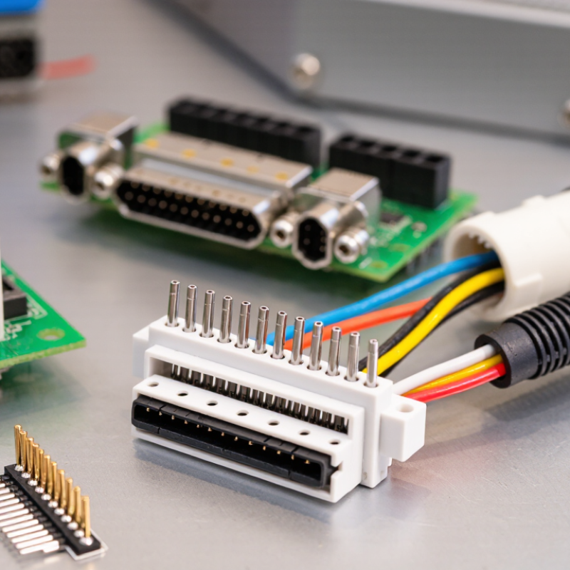
| Basic Definition | Connector designation | “2510” commonly refers to a 2.54 mm pitch wire-to-board connector family. The designation is not a universal industry standard and may describe different mechanical versions. | Confirm the manufacturer’s drawing, terminal arrangement, locking features, and mating dimensions before treating two 2510 connectors as interchangeable. |
| Basic Definition | Contact pitch | 2.54 mm center-to-center spacing between adjacent contacts. | Use the same 2.54 mm pitch on the PCB header and the cable housing. A similar-looking connector with a different pitch will not mate correctly. |
| Top Type | Single-row wire-to-board housing | Usually available in approximately 2 to 20 circuits, depending on the series and tooling. | Suitable for compact control wiring, signal distribution, LED modules, sensors, and internal equipment connections. |
| Top Type | Dual-row wire-to-board housing | Often offered in higher circuit counts while maintaining a 2.54 mm contact pitch within each row. | Select a dual-row version only when the mating PCB header, keying, row spacing, and overall housing dimensions match. |
| Top Type | Vertical PCB header | Pins extend perpendicular to the PCB surface; straight pin lengths commonly support through-hole or board-mount designs. | Choose this style when the cable approaches the board from above or when the assembly requires a compact vertical profile. |
| Top Type | Right-angle PCB header | Pins extend parallel to the PCB surface after soldering, allowing the cable to exit horizontally. | Use it when enclosure height is limited. Check the cable bend radius and the header’s horizontal clearance. |
| Top Type | Pre-crimped wire assembly | A housing fitted with crimp contacts and discrete wires, commonly supplied in custom lengths and circuit counts. | Useful for production harnesses. Verify wire length, polarity, contact retention, pull force, and terminal insertion depth. |
| Electrical | Rated voltage | Common low-voltage ratings are approximately 100 to 250 V AC/DC, but the actual rating depends on insulation, spacing, and test standard. | Use the lower applicable rating when the product is subject to pollution, humidity, altitude, or safety requirements. Always confirm the exact datasheet value. |
| Electrical | Rated current | Typical values are approximately 1 to 3 A per contact with suitable wire and temperature conditions. | Current capacity decreases with smaller wire, higher ambient temperature, multiple energized contacts, and inadequate PCB copper. Apply derating where required. |
| Electrical | Contact resistance | Often specified at no more than approximately 20 mΩ when new and tested under defined conditions. | Low contact resistance supports reliable signal and low-power connections. Contamination, oxidation, poor crimping, and repeated mating can increase resistance. |
| Electrical | Insulation resistance | Common minimum specifications are in the 100 MΩ range or higher after standard conditioning tests. | For high-impedance or low-level signals, check insulation resistance after humidity, temperature, and voltage testing rather than relying only on the initial value. |
| Mechanical | Compatible wire size | Commonly approximately 22–28 AWG, depending on the terminal design and conductor type. | Match the terminal to the conductor diameter and insulation outside diameter. Use the specified crimp height and an approved crimping tool. |
| Mechanical | Contact retention | Female contacts are normally held inside the housing by a primary locking lance; some designs also include a secondary retainer. | After insertion, perform a gentle pull test on each wire. Do not force a terminal that is not fully aligned with the housing cavity. |
| Mechanical | Mating system | Usually a friction-fit or positive-locking connection using a header pin and crimp socket contact. | A positive lock is preferable for vibration or serviceable equipment. Confirm the locking direction and required unmating force. |
| Materials | Insulator material | Common choices include nylon or other engineering thermoplastics, with flammability grades such as UL94 V-0 available on some versions. | Select the material according to operating temperature, flame rating, chemical exposure, and applicable equipment safety requirements. |
| Materials | Contact material and finish | Copper-alloy contacts are common; tin plating is widely used for general-purpose applications, while other finishes may be available for special environments. | Tin-plated contacts should be kept clean and properly mated. Choose a finish suitable for corrosion, fretting, or low-level signal requirements. |
| Environment | Operating temperature | A common range is approximately −25°C to +85°C, while high-temperature versions may extend to about +105°C. | The system limit is determined by the connector, wire insulation, PCB, and surrounding components. Use the lowest applicable temperature rating. |
| Environment | Vibration and shock | Performance depends on the locking structure, terminal retention, PCB mounting, and wire strain relief. | For mobile or vibrating equipment, use a positive-lock housing, secure the cable, and avoid placing bending force directly on the contact crimp. |
| Application | Typical uses | Control panels, power distribution inside equipment, display modules, lighting assemblies, sensors, fans, small motors, and embedded electronics. | Use for low-voltage internal interconnections unless the exact product has been evaluated and approved for the intended mains or safety-critical application. |
| Selection | Circuit count | Select the required number of positions, with spare circuits added when future expansion or service access is expected. | Check whether unused cavities require plugs, seals, or electrical isolation. Confirm that the selected circuit count matches the PCB layout. |
| Selection | Keying and polarity | Some housings use a polarized shape, locating bosses, or a locking tab to prevent reverse insertion. | Prefer keyed or polarized designs where reverse connection could damage the circuit. Mark pin 1 clearly on both the PCB and harness. |
| Selection | PCB footprint | The footprint must match 2.54 mm pitch, pin diameter, row configuration, mounting style, and recommended hole or pad dimensions. | Follow the selected component’s land pattern rather than copying a generic 2.54 mm footprint. Verify solder fillets and assembly clearances. |
| Installation | Crimping procedure | Strip the specified insulation length, place the conductor and insulation in the correct terminal areas, then crimp with the correct die. | Avoid solder buildup on crimp contacts unless specifically permitted. Inspect conductor wings, insulation support, bell mouth, and exposed strands. |
| Installation | Inspection before mating | Check terminal alignment, housing damage, bent header pins, correct wire sequence, and complete terminal insertion. | Mate the connector straight and evenly. Stop if excessive force is required because incorrect keying or misalignment may cause permanent damage. |
| Reliability | Mating cycles | General-purpose versions may be designed for tens of mating cycles; the exact number varies by contact plating and construction. | For frequent maintenance, select a connector specifically rated for repeated mating and avoid using the cable as a handle during disconnection. |
| Final Check | Recommended verification | Confirm pitch, circuit count, pin arrangement, current, voltage, wire range, temperature, locking, footprint, and applicable approvals. | Because “2510” is a family-style designation rather than a single universal specification, verify the exact part drawing and test conditions before production use. |



 Close