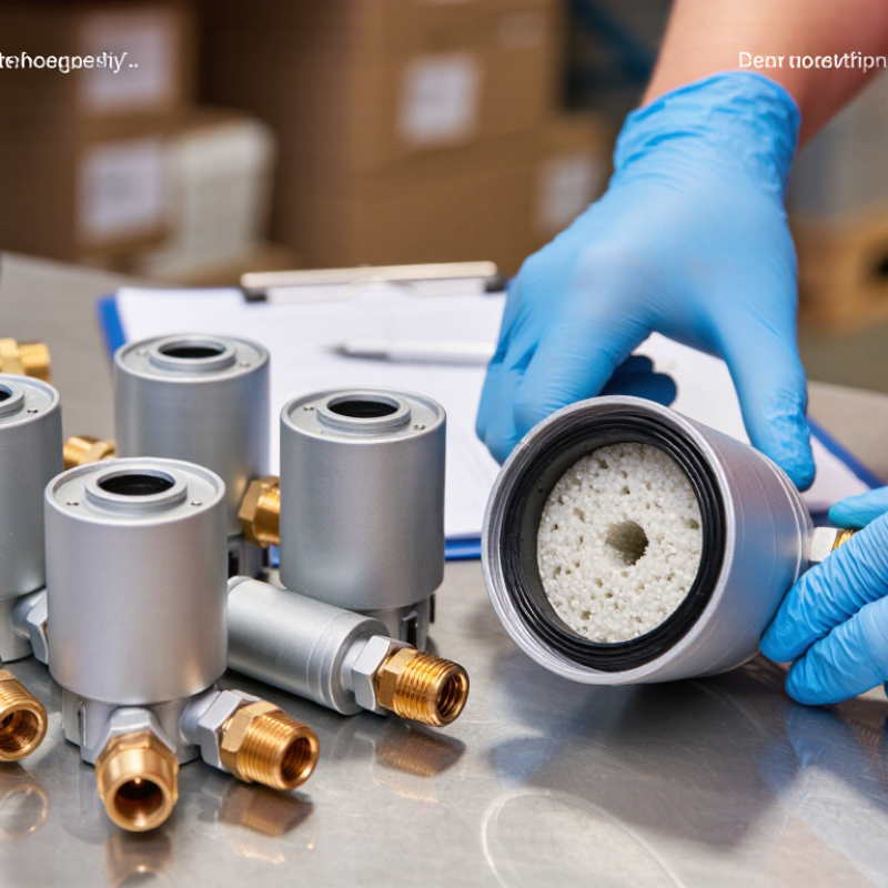
| Primary Function | A filter drier removes moisture, acid, particulate matter, and other harmful contaminants from a refrigeration or air-conditioning system. | Protects the compressor, expansion device, valves, bearings, and refrigerant circuit from contamination-related damage. | Confirm that the product is designed for the intended refrigeration system and contamination-control requirements. |
| Typical Installation Location | Most filter driers are installed in the liquid line, generally downstream of the condenser and upstream of the metering device. | Prevents moisture and solid particles from reaching sensitive expansion components. | Check flow direction, installation position, line size, service clearance, and compatibility with the system layout. |
| Suction-Line Application | Special suction-line filter driers are used mainly after a compressor burnout or when substantial system contamination is present. | Captures acids, carbonized oil, and debris before they return to the replacement or repaired compressor. | Verify that the model is specifically rated for suction-line use and has an acceptable pressure drop at the required mass flow. |
| Construction Type | Common designs include sealed solid-core units, replaceable-core shells, and bi-flow filter driers. | Construction determines serviceability, flow direction, contaminant capacity, and suitability for different system architectures. | Select a sealed unit for compact systems or a replaceable-core shell where inspection and maintenance are expected. |
| Desiccant Core | Desiccant materials commonly include molecular sieve, activated alumina, or blended formulations selected for moisture and acid control. | Adsorbs water and, depending on the formulation, helps reduce acids and other reactive contaminants. | Request desiccant type, moisture-removal data, acid-removal performance, and compatibility with the refrigerant and oil. |
| Filtration Rating | The internal filter structure retains solid particles generated during manufacturing, installation, wear, brazing, or component failure. | Reduces the risk of blocked metering devices, valve wear, and abrasive damage. | Ask for the tested particle-retention rating and confirm whether the rating applies to liquid-line or suction-line service. |
| Flow Direction | Standard liquid-line units normally use one-way flow, while heat-pump and reversing systems may require bi-directional flow capability. | Maintains filtration and drying performance when the refrigerant direction changes. | For reversible systems, verify bi-flow approval, pressure-drop data in both directions, and correct installation orientation. |
| Refrigerant Compatibility | Compatibility depends on the refrigerant, lubricant, operating pressure, temperature range, and internal sealing materials. | Prevents chemical degradation, swelling, leakage, and loss of drying performance. | Obtain a compatibility list covering the exact refrigerant and oil combination used in the equipment. |
| Moisture-Control Capacity | Moisture capacity is affected by desiccant formulation, refrigerant type, liquid temperature, moisture concentration, and flow conditions. | Keeps dissolved and free moisture below levels that can cause freezing, corrosion, hydrolysis, or acid formation. | Compare tested capacity at the specified refrigerant, temperature, and moisture condition rather than relying only on physical size. |
| Pressure Drop | Pressure drop varies with connection size, refrigerant mass flow, liquid density, filter loading, and flow direction. | Low pressure drop supports efficient system operation and helps maintain the required liquid or suction conditions. | Request pressure-drop curves for the actual refrigerant, capacity range, and operating temperature. |
| Pressure and Temperature Limits | Each unit has defined maximum working pressure, allowable temperature range, and sometimes maximum operating pressure for specific refrigerants. | Maintains mechanical integrity and safe operation throughout the refrigeration cycle. | Check the technical datasheet, nameplate, pressure rating, temperature rating, and applicable regional safety requirements. |
| Connection Options | Common connection formats include copper sweat, flare, and threaded or brazed connections, depending on the product design and market. | Provides mechanical and leak-tight integration with the refrigerant piping. | Match connection type, nominal line size, tubing outside diameter, installation method, and available service tools. |
| Replaceable-Core Service | Replaceable-core shells allow the internal core to be changed without replacing the complete shell. | Supports repeated contamination removal, system commissioning, and maintenance in larger installations. | Confirm core availability, sealing-gasket requirements, service procedure, isolation-valve arrangement, and maintenance intervals. |
| System Capacity Matching | Filter drier selection should be based on refrigerant mass flow, system capacity, line size, temperature, and acceptable pressure drop. | Prevents undersizing, excessive restriction, and inadequate moisture or contaminant control. | Use manufacturer capacity tables and select by operating conditions, not by connection size alone. |
| Installation Practice | The refrigeration circuit should be clean, dry, properly evacuated, and protected from contamination during brazing and assembly. | Extends filter-drier service life and reduces the contaminant load entering the system. | Confirm installation instructions, brazing guidance, flow-arrow marking, storage condition, and recommended evacuation procedure. |
| Documentation for Global Purchasing | Typical technical documents include datasheets, dimensional drawings, pressure-drop charts, compatibility information, test reports, and installation instructions. | Supports engineering approval, import clearance, installation, quality control, and after-sales service. | Request complete product documentation, material information, batch traceability, packaging details, and applicable conformity declarations. |



 Close