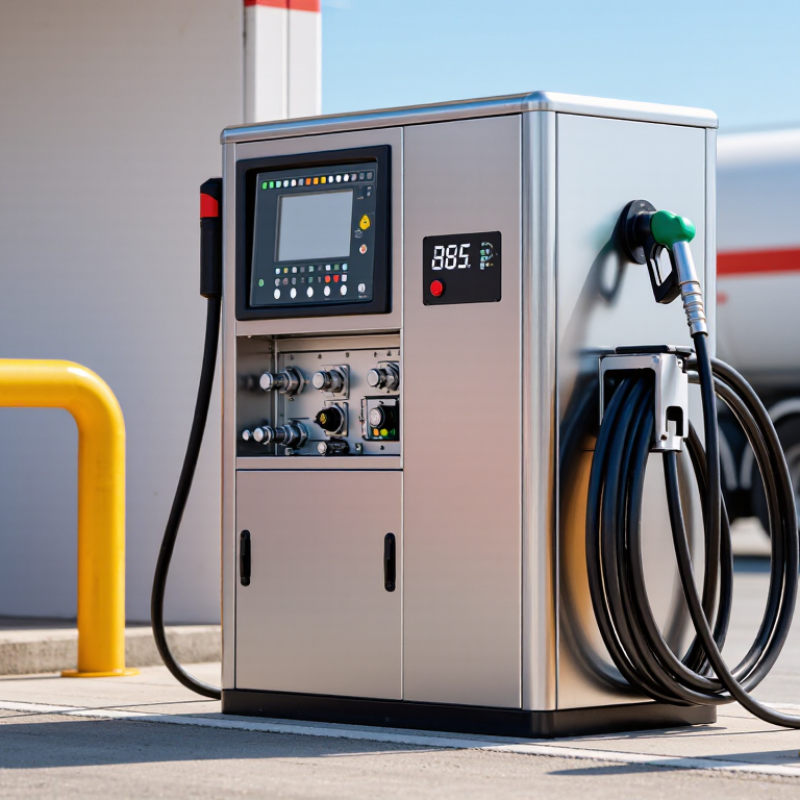
| Single-line, single-hose configuration | A dispenser arrangement with one LNG product-delivery line and one fueling hose. “Single-line, single-hose” describes the delivery configuration rather than a standardized metering or pump technology. | One LNG supply connection, product piping, isolation and control valves, metering assembly, one cryogenic hose, fueling coupling or nozzle, controller, and safety devices. | The term refers to the LNG delivery path. Vapor management may be handled by the station system or by a separately designed arrangement; it should not be assumed from the number of product hoses alone. |
| Coriolis mass-metered dispenser | Measures LNG mass flow directly using a Coriolis flow meter. Mass measurement avoids relying solely on a volume reading that can vary with fluid density and temperature. | Cryogenic-compatible Coriolis meter, transmitter or flow computer, control valve, piping, hose assembly, and dispenser controller or display. | Meter selection and installation should account for the meter’s approved operating envelope, pressure drop, vibration, calibration requirements, and applicable legal-metrology rules. |
| Volume-metered dispenser | Measures the volume of LNG delivered. If billing or reporting is required by mass, the system needs an appropriate method to determine or calculate mass using validated density and temperature information. | Cryogenic-compatible volume meter, temperature and density inputs where required, calculator or flow computer, valves, hose, and controller. | Measurement performance depends on the meter technology and the fluid conditions. The measurement method must be suitable for LNG service and accepted by the relevant authorities. |
| Pump-supplied dispenser | Receives pressurized LNG from a station system that uses a cryogenic pump to provide the required delivery pressure and flow. | Station cryogenic pump, supply piping, pressure and temperature instrumentation, dispenser isolation and control valves, meter, hose, and fueling coupling. | The pump is typically part of the station supply system, not necessarily inside the dispenser cabinet. System design must manage pressure, cool-down, and safe operating limits. |
| Pressure-fed dispenser | Receives LNG driven by a pressure differential established by the upstream storage or station system, rather than by a dedicated pump at the dispenser. | Pressurized LNG source, supply piping, pressure-control and isolation valves, meter, hose, coupling, and monitoring instruments. | Available flow depends on the station pressure conditions and system design. A pressure-fed arrangement is not interchangeable with a pump-fed arrangement in every installation. |
| Dispenser with integrated metering and control | Combines the meter interface, transaction controller, operator display, and associated control functions within the dispenser assembly. | Meter or meter transmitter, flow computer or controller, display, communications interface, valve controls, and emergency-stop interface. | Integration can simplify local operation, but electrical equipment, enclosure design, communications, and hazardous-area requirements must be addressed for the installation. |
| Dispenser with remote metering or control | Places some measurement-processing or supervisory-control functions in a separate station cabinet or control system, while the dispenser provides the required field connections and interfaces. | Field meter and sensors, local valves and safety devices, signal or communications connections, remote flow computer or controller, and operator interface. | Signal integrity, system compatibility, fail-safe behavior, and clear allocation of safety functions should be specified between the dispenser and station control system. |
| Common safety and delivery assembly | The cryogenic product path and safety functions shared by many single-hose dispenser designs. | Insulated or otherwise LNG-suitable piping, cryogenic valves, hose, fueling coupling, breakaway device where required by the design, pressure and temperature sensors, grounding provisions, and emergency-stop or shutdown interface. | Components must be suitable for the specified cryogenic temperatures, pressure, materials, and service conditions. The complete installation requires a coordinated safety design and applicable code compliance. |



 Close