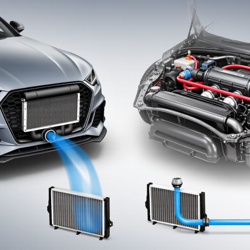
| How it works | Charge air flows through tubes while ambient air passes over external fins, carrying heat away. | Charge air passes through stacked passages separated by plates; ambient air flows through the other passages to remove heat. | Charge air transfers heat to a liquid coolant in a compact core. The warmed coolant then releases heat through a separate heat exchanger. |
| Typical strengths | Often offers low weight, a relatively simple installation, and effective cooling when mounted in a strong airflow. | Often provides a robust core and substantial heat-transfer area in a given frontal size; suitable designs can handle demanding use. | Can place the charge-air cooler close to the engine, allowing short intake plumbing and flexible packaging. |
| Packaging and airflow | Needs a position with good ambient airflow, such as the front of the vehicle. Long charge-air pipes may be needed depending on the layout. | Also depends on airflow through the vehicle’s front end. Core thickness and placement must be balanced against airflow to other heat exchangers. | The charge-air core can be located where space is available, but the system still needs a coolant heat exchanger with adequate airflow. |
| Heat management in repeated use | Can perform consistently when it receives adequate airflow and is correctly sized. Heat soak can occur at low vehicle speed or during repeated high-load operation. | Performance depends on core design, airflow, and sizing. A larger or denser core is not automatically better if it restricts airflow or adds excessive pressure loss. | Coolant provides a buffer against short heat spikes, but repeated high-load use can warm the coolant. Sustained performance depends on the coolant radiator, pump, and system capacity. |
| Charge-air plumbing | Pipe length and routing depend on the vehicle layout; longer pipes can add volume and create packaging challenges. | Usually uses a similar charge-air routing approach to other air-to-air systems; the core construction itself does not determine pipe length. | Can use shorter charge-air pipes when the core is mounted near the engine, though coolant lines and electrical or mechanical pump connections are added. |
| System complexity | Generally the simplest of these layouts: the charge-air core and airflow path are the main requirements. | Generally similar in system complexity to a tube-and-fin air-to-air arrangement; construction and core design affect cost and weight. | More components are required, typically including a coolant pump, reservoir or fill point, hoses, and a separate heat exchanger. |
| Weight and maintenance considerations | Often a lighter option, although actual weight depends on core size and materials. Keep the core clear of debris and inspect for leaks or damage. | Can be heavier than a comparable tube-and-fin core, depending on its construction and size. Inspect for impact damage, leaks, and blocked airflow. | Adds coolant and components, increasing system complexity and potentially weight. Coolant condition, pump operation, and hose connections need attention. |
| Often a good fit for | Road vehicles with good front-end airflow, where simplicity, low weight, and straightforward servicing are priorities. | Applications needing a sturdy air-to-air core, provided there is enough space and airflow for the selected core. | Vehicles with limited space for long charge-air pipes, or layouts where a remotely mounted coolant heat exchanger is practical. |
| Main trade-off | Cooling effectiveness relies strongly on ambient airflow and suitable core placement. | Core strength and heat-transfer area must be weighed against size, weight, airflow restriction, and pressure drop. | Compact charge-air packaging comes with added components and the need to manage coolant temperature under sustained load. |
| Best choice depends on | Engine output, duty cycle, available space, ambient conditions, airflow, allowable pressure drop, charge-pipe layout, and the quality of the complete installation. No design is best for every vehicle. |



 Close