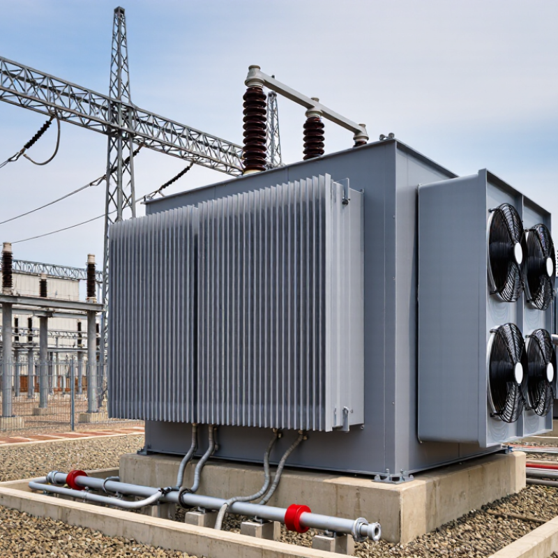
| Definition | Primary function | A grounding transformer creates an artificial neutral point on a three-phase system that does not have a directly accessible neutral. | It enables controlled connection of the system to earth and provides a defined path for zero-sequence current during an earth fault. |
| Operating Principle | Fault-current path | During a single-line-to-ground fault, current flows through the phase conductor, the fault point, the grounding connection, and the transformer neutral path. | A predictable fault path allows protection systems to detect and clear faults more reliably. |
| Common Design | Zig-zag configuration | A zig-zag grounding transformer provides a neutral point and offers a low-impedance path to zero-sequence current while generally presenting higher impedance to balanced three-phase current. | It is often selected when a compact grounding solution is required without a conventional secondary load winding. |
| Common Design | Wye-delta configuration | The grounded wye side provides the neutral connection, while the delta side can circulate triplen-frequency components and may supply auxiliary power when specifically designed for that purpose. | This arrangement can combine system grounding with a usable low-voltage auxiliary supply. |
| Neutral Grounding | Neutral grounding resistor | A resistor connected between the transformer neutral and earth limits ground-fault current to a selected value. | Limiting current reduces thermal and mechanical damage while maintaining enough current for protective relays to identify the fault. |
| Example Calculation | Ground-fault current | For an 11 kV line-to-line system with a 20 Ω neutral grounding resistor: I ≈ 11,000 ÷ (√3 × 20) = 317.5 A, excluding system and transformer impedance. | The calculation helps buyers compare resistor ratings, relay settings, earthing conductors, and short-time thermal withstand requirements. |
| Grounding Method | Solid grounding | The neutral is connected to earth with negligible intentional impedance, allowing relatively high earth-fault current. | It supports fast fault clearing but may increase equipment stress and requires suitable interrupting and grounding capacity. |
| Grounding Method | Low-resistance grounding | The neutral resistor is selected to permit a comparatively high but controlled fault current, commonly in the hundreds of amperes for medium-voltage industrial systems. | It provides strong relay sensitivity while limiting damage compared with solid grounding. |
| Grounding Method | High-resistance grounding | The neutral resistor limits the fault current to a low value, often near or below the system’s charging-current level, subject to the network design. | It can reduce arc-flash energy and allow continued operation for a limited period, but requires sensitive ground-fault monitoring. |
| Protection | Zero-sequence protection | Grounding transformers support measurement of zero-sequence voltage or current, which is used by earth-fault relays and ground-fault protection systems. | Protection settings can be coordinated with the selected transformer impedance and neutral grounding resistor. |
| System Compatibility | Typical applications | Common applications include medium-voltage distribution networks, industrial plants, renewable-energy collector systems, mining facilities, and isolated three-phase networks. | Application type determines the required voltage rating, fault-current duration, insulation level, enclosure, cooling, and protection scheme. |
| Rating | Continuous and short-time duty | A grounding transformer is normally sized for the required ground-fault current and its duration, rather than for the full continuous load of the connected power system. | Buyers should specify continuous duty, short-time current, duration, temperature rise, and permissible neutral displacement separately. |
| Technical Standards | Specification framework | Relevant project requirements may reference IEC 60076-6 for reactors, IEC 61936-1 for power installations above 1 kV AC, IEEE 32 for neutral grounding devices, and applicable local grid codes. | Using the correct regional standards improves tender comparability, inspection planning, certification, and project approval. |
| Buyer Checklist | Key parameters to request | System voltage, frequency, grounding method, neutral current, fault duration, transformer connection, impedance, insulation level, enclosure rating, cooling method, environmental conditions, and applicable standard. | A complete specification reduces redesign risk, prevents mismatched protection settings, and supports reliable operation across different grid conditions. |



 Close
Close